


9
82575 Ethernet Controller Design Guide
3.2.1 LAN Disable for 82575 Ethernet Controller Gigabit Ethernet
Controller
The 82575 Ethernet Controller device has three signals that can be used for disabling
Ethernet functions from system BIOS. LAN0_DIS_N and LAN1_DIS_N are the
separated port disable signals and DEV_OFF_N is the device disable signal. Each signal
can be driven from a system output port. Choose outputs from devices that retain their
values during reset. For example, ICH7 resumes GPIO outputs (GP24, 25, 27, 28)
transition high during reset. It is important not to use these signals to drive
LAN0_DIS_N or LAN1_DIS_N because these inputs are latched upon the rising edge of
PE_RST_N or an inband reset end. The DEV_OFF_N input is completely asynchronous
and does not have this restriction.
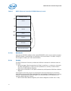
Each PHY may be disabled if its LAN function's LAN Disable input indicates that the
relevant function should be disabled. Since the PHY is shared between the LAN function
and manageability, it may not be desired to power down the PHY in LAN Disable. The
PHY_in_LAN_Disable EEPROM bit determines whether the PHY (and MAC) are powered
down when the LAN Disable pin is asserted. Default is not to power down.
A LAN port may also be disabled through EEPROM settings. If the LAN_DIS EEPROM bit
is set, the PHY enters power down. Note, however, that setting the EEPROM
LAN_PCI_DIS bit does not bring the PHY into power down.
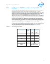
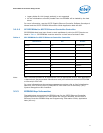
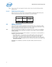
Table 1. PCI/LAN Function Index
PCI Function #
LAN
Function
Select
Function 0 Function 1
Both LAN functions are
enabled
0 LAN 0 LAN 1
LAN 0 is disabled 0 Dummy LAN1
LAN 1 is disabled 0 LAN 0 -
LAN 0 is disabled 1 LAN 1 -
Both LAN functions are
enabled
1 LAN 1 LAN 0
LAN 1 is disabled 1 Dummy LAN 0
Both LAN functions are
disabled
Don’t Care
All PCI functions are
disabled
Whole Device is at deep
PD