


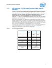

7
82575 Ethernet Controller Design Guide
3.0 Ethernet Component Design Guidelines
These sections provide recommendations for selecting components and connecting
special pins.
For 1000 BASE-T designs, the main design elements are the 82575 Gigabit Ethernet
Controller, an integrated discrete or magnetics module with RJ-45 connector, an
EEPROM, and a clock source.
3.1 General Design Considerations for Ethernet Controllers
Follow good engineering practices with respect to unused inputs by terminating them
with pull-up or pull-down resistors, unless the datasheet, design guide or reference
schematic indicates otherwise. Do not attach pull-up or pull-down resistors to any balls
identified as No Connect. These devices may have special test modes that could be
entered unintentionally.
3.1.1 Clock Source
All designs require a 25 MHz clock source. The 82575 Gigabit Ethernet Controller uses
the 25 MHz source to generate clocks up to 125 MHz and 1.25 GHz for the PHY circuits,
and 1.25 GHz for the SERDES. For optimum results with lowest cost, connect a 25 MHz
parallel resonant crystal and appropriate load capacitors at the XTAL1 and XTAL2 leads.
The frequency tolerance of the timing device should be 30 ppm or better. Refer to the
application note, Intel Fast Ethernet Controllers Timing Device Selection Guide, AP-419,
for more information on choosing crystals.
For further information regarding the clock for the 82575, see the sections about
frequency control, crystals, and oscillators later in this document.
3.1.2 Magnetics for 1000 BASE-T
Magnetics for the 82575 can be either integrated or discrete.
The magnetics module has a critical effect on overall IEEE and emissions conformance.
The device should meet the performance required for a design with reasonable margin
to allow for manufacturing variation. Occasionally, components that meet basic
specifications may cause the system to fail IEEE testing because of interactions with
other components or the printed circuit board itself. Carefully qualifying new magnetics
modules prevents this problem.
When using discrete magnetics it is necessary to use Bob Smith termination: Use four
75 Ω resistors for cable-side center taps and unused pins. This method terminates pair-
to-pair common mode impedance of the CAT5 cable.
Use an EFT capacitor attached to the termination plane. Suggested values are 1500 pF/
2KV or 1000 pF/3KV. A minimum of 50-mil spacing from capacitor to traces and
components should be maintained.
3.1.2.1 Magnetics Module Qualification Steps
The steps involved in magnetics module qualification are similar to those for crystal
qualification:
1. Verify that the vendor’s published specifications in the component datasheet meet
or exceed the required IEEE specifications.
2. Independently measure the component’s electrical parameters on the test bench,
checking samples from multiple lots. Check that the measured behavior is