


39
82575 Ethernet Controller Design Guide
7.0 Ethernet Component Layout Guidelines
These sections provide recommendations for performing printed circuit board layouts.
Good layout practices are essential to meet IEEE PHY conformance specifications and
EMI regulatory requirements.
7.1 Layout Considerations for 82575 Ethernet Controllers
Critical signal traces should be kept as short as possible to decrease the likelihood of
being affected by high frequency noise from other signals, including noise carried on
power and ground planes. Keeping the traces as short as possible can also reduce
capacitive loading.
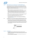
Since the transmission line medium extends onto the printed circuit board, special
attention must be paid to layout and routing of the differential signal pairs.
Designing for 1000 BASE-T Gigabit operation is very similar to designing for 10 and 100
Mbps. For the 82575 Gigabit Ethernet controller, system level tests should be
performed at all three speeds.
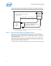
7.1.1 Guidelines for Component Placement
Component placement can affect signal quality, emissions, and component operating
temperature This section provides guidelines for component placement.
Careful component placement can:
• Decrease potential problems directly related to electromagnetic interference (EMI),
which could cause failure to meet applicable government test specifications.
• Simplify the task of routing traces. To some extent, component orientation will
affect the complexity of trace routing. The overall objective is to minimize turns and
crossovers between traces.