


47
82575 Ethernet Controller Design Guide
• Isolate I/O signals from high-speed signals to minimize crosstalk, which can
increase EMI emission and susceptibility to EMI from other signals.
• Avoid routing high-speed LAN traces near other high-frequency signals associated
with a video controller, cache controller, processor, or other similar devices.
7.1.11 Power and Ground Planes
Good grounding requires minimizing inductance levels in the interconnections and
keeping ground returns short, signal loop areas small, and power inputs bypassed to
signal return, will significantly reduce EMI radiation.
The following guidelines help reduce circuit inductance in both backplanes and
motherboards:
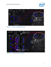
• Route traces over a continuous plane with no interruptions. Do not route over a
split power or ground plane. If there are vacant areas on a ground or power plane,
avoid routing signals over the vacant area. This will increase inductance and EMI
radiation levels.
• Separate noisy digital grounds from analog grounds to reduce coupling. Noisy
digital grounds may affect sensitive DC subsystems.
• All ground vias should be connected to every ground plane; and every power via
should be connected to all power planes at equal potential. This helps reduce circuit
inductance.
• Physically locate grounds between a signal path and its return. This will minimize
the loop area.
• Avoid fast rise/fall times as much as possible. Signals with fast rise and fall times
contain many high frequency harmonics, which can radiate EMI.
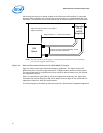
• The ground plane beneath a magnetics module should be split. The RJ45 connector
side of the transformer module should have chassis ground beneath it.
7.1.12 Traces for Decoupling Capacitors
Traces between decoupling and I/O filter capacitors should be as short and wide as
practical. Long and thin traces are more inductive and would reduce the intended effect
of decoupling capacitors. Also for similar reasons, traces to I/O signals and signal
terminations should be as short as possible. Vias to the decoupling capacitors should be
sufficiently large in diameter to decrease series inductance.
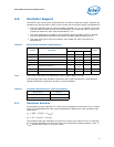
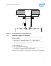
7.1.13 Light Emitting Diodes for Designs Based on the 82575
Controller
The 82575 controller provides four programmable high-current push-pull (active high)
outputs per port to directly drive LEDs for link activity and speed indication. Each LAN
device provides an independent set of LED outputs; these pins and their function are
bound to a specific LAN device. Each of the four LED outputs can be individually
configured to select the particular event, state, or activity, which will be indicated on
that output. In addition, each LED can be individually configured for output polarity, as
well as for blinking versus non-blinking (steady-state) indication.
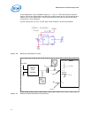
Since the LEDs are likely to be integral to a magnetics module, take care to route the
LED traces away from potential sources of EMI noise. In some cases, it may be
desirable to attach filter capacitors.
The LED ports are fully programmable through the EEPROM interface.