


82575 Ethernet Controller Design Guide
34
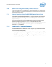
An allowance of 3 pF to 7 pF accounts for lumped stray capacitance. The calculated load
capacitance is 16 pF with an estimated stray capacitance of about 5 pF.
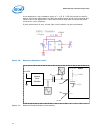
Individual stray capacitance components can be estimated and added. For example,
surface mount pads for the load capacitors add approximately 2.5 pF in parallel to each
capacitor. This technique is especially useful if Y1, C1 and C2 must be placed farther
than approximately one-half (0.5) inch from the device. It is worth noting that thin
circuit boards generally have higher stray capacitance than thick circuit boards. Consult
the PCIe Design Guide for more information.
The oscillator frequency should be measured with a precision frequency counter where
possible. The load specification or values of C1 and C2 should be fine tuned for the
design. As the actual capacitance load increases, the oscillator frequency decreases.
Note: C1 and C2 may vary by as much as 5% (approximately 1 pF) from their nominal
values.
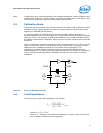
5.7 Shunt Capacitance
The shunt capacitance parameter is relatively unimportant compared to load
capacitance. Shunt capacitance represents the effect of the crystal’s mechanical holder
and contacts. The shunt capacitance should equal a maximum of 7 pF.
5.8 Equivalent Series Resistance
Equivalent Series Resistance (ESR) is the real component of the crystal’s impedance at
the calibration frequency, which the inverting amplifier’s loop gain must overcome. ESR
varies inversely with frequency for a given crystal family. The lower the ESR, the faster
the crystal starts up. Use crystals with an ESR value of 50 Ω or better.
5.9 Drive Level
Drive level refers to power dissipation in use. The allowable drive level for a Surface
Mounted Technology (SMT) crystal is less than its through-hole counterpart, because
surface mount crystals are typically made from narrow, rectangular AT strips, rather
than circular AT quartz blanks.
Some crystal data sheets list crystals with a maximum drive level of 1 mW. However,
Intel Ethernet controllers drive crystals to a level less than the suggested 0.5 mW
value. This parameter does not have much value for on-chip oscillator use.
5.10 Aging
Aging is a permanent change in frequency (and resistance) occurring over time. This
parameter is most important in its first year because new crystals age faster than old
crystals. Use crystals with a maximum of ±5 ppm per year aging.
5.11 Reference Crystal
The normal tolerances of the discrete crystal components can contribute to small
frequency offsets with respect to the target center frequency. To minimize the risk of
tolerance-caused frequency offsets causing a small percentage of production line units
to be outside of the acceptable frequency range, it is important to account for those
shifts while empirically determining the proper values for the discrete loading
capacitors, C1 and C2.