


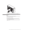
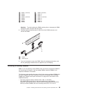
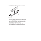
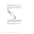
1 Power supply
2 Power-supply handle
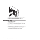
4. Remove the air baffle (see “Removing the air baffle” on page 44).
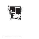
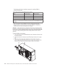
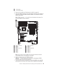
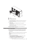
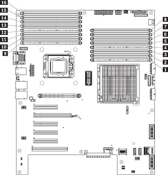
5. Locate the DIMM connectors on the system board. Determine the connector in
which you will install the DIMM. Install the DIMMs in the sequence indicated
earlier in this section.
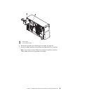
Note: DIMM connectors 1, 4, 9, and 12 are not functional in this server. Do
not install DIMMs in these connectors.
1 DIMM 1 (reserved) 9 DIMM 9 (reserved)
2 DIMM 2 10 DIMM 10
3 DIMM 3 11 DIMM 11
4 DIMM 4 (reserved) 12 DIMM 12 (reserved)
5 DIMM 5 13 DIMM 13
6 DIMM 6 14 DIMM 14
7 DIMM 7 15 DIMM 15
8 DIMM 8 16 DIMM 16
Note: Do not insert memory DIMMs into connectors marked as reserved.
These DIMM slots are not supported in this model.
6. Open the retaining clips on the DIMM connector.
Attention: To avoid breaking the retaining clips or damaging the DIMM
connectors, open and close the clips gently.
7. Touch the static-protective package that contains the DIMM to any unpainted
metal surface on the server; then, remove the new DIMM from the package.
Chapter 5. Installing optional devices and replacing customer replaceable units 93