


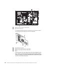
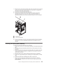
9. Disconnect the control-panel assembly cable from the system board, noting the
routing of the cable (see “System-board internal connectors” on page 28 for
the location of the front panel connector).
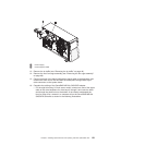
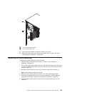
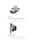
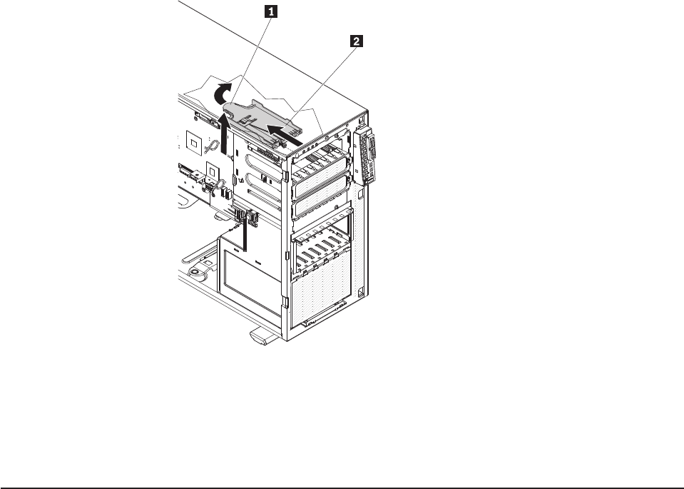
10. Locate the control-panel assembly release latch.
11. Press down the release latch of the control-panel assembly and pull the
assembly toward the rear of the server. After you pull the assembly out
approximately halfway, start turning it downward and pull it out of the chassis.
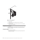
1 Release latch
2 Control panel assembly
12. If you are instructed to return the control-panel assembly, follow all packaging
instructions, and use any packaging materials that are supplied to you for
shipping.
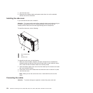
Installing the control-panel assembly
To install the control-panel assembly, do the following:
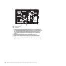
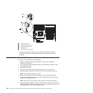
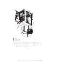
1. Position the front end of the control-panel assembly in the channel above drive
bay 1.
2. Slide the control-panel assembly toward the front of the chassis until it clicks
into place.
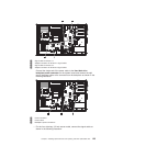
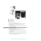
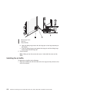
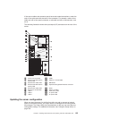
3. Route and connect the control-panel assembly cable to the system board (see
“System-board internal connectors” on page 28 for the location of the front
control panel connector).
4. Slide the drives in bay 1 and bay 2 back into the drive bays, if necessary.
5. Install the fan cage assembly (see “Installing the fan cage assembly” on page
47y).
6. Install the air baffle (see “Installing the air baffle” on page 132).
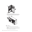
7. Rotate the power-supply cage assembly back into the server. Press the
power-supply cage release tab and rotate the power-supply cage assembly
into the chassis.
Chapter 5. Installing optional devices and replacing customer replaceable units 129