


If the server cables and connector panel have color-coded connections, match the
color of the cable end with the color of the connector. For example, match a blue
cable end with a blue panel connector, a red cable end with a red connector, and
so on.
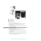
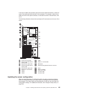
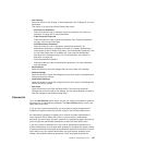
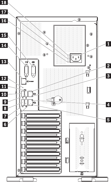
The following illustration shows the input/output (I/O) connectors on the rear of the
server.
1 Power cord connector 10 USB 1
2 Ethernet transmit/receive
activity LED
11 Ethernet 1 10/100/1000
3 Ethernet link status LED 12 NMI button
4 Ethernet transmit/receive
activity LED
13 Systems-management Ethernet connector
5 Ethernet link status LED 14 Video
6 Ethernet 2 10/100/1000 15 Serial 1 (COM 1)
7 USB 4 16 Fault (error) LED
8 USB 3 17 ac power LED
9 USB 2 18 dc power LED
Updating the server configuration
When you start the server for the first time after you add or remove an internal
option or an external device, you might receive a message that the configuration
has changed. The Setup Utility starts automatically so that you can save the new
configuration settings. For additional information, see “Using the Setup Utility” on
page 138.
Chapter 5. Installing optional devices and replacing customer replaceable units 135