


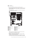
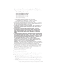
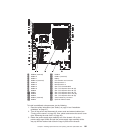
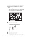
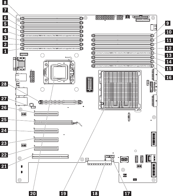
1 DIMM 9 (reserved) 15 DIMM 2
2 DIMM 10 16 DIMM 1 (reserved)
3 DIMM 11 17 Battery
4 DIMM 12 (reserved) 18 PCI extender card connector
5 DIMM 13 19 Microprocessor 1
6 DIMM 14 20 Microprocessor 2
7 DIMM 15 21 Slot 6, PCI 32 bit/33 MHz
8 DIMM 16 22 Slot 5, PCI Express Gen2 x8 (x8)
9 DIMM 8 23 Slot 4, PCI Express Gen2 x8 (x4)
10 DIMM 7 24 Slot 3, PCI Express Gen2 x8 (x4)
11 DIMM 6 25 Slot 2, PCI Express Gen2 x18 (x8)
12 DIMM 5 26 Slot 1, PCI Express Gen2 x8 (x8)
13 DIMM 4 (reserved) 27 Virtual media key connector
14 DIMM 3 28 Optional VRM connector
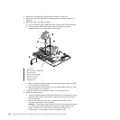
To install an additional microprocessor, do the following:
1. Read the safety information (see “Safety” on page vii and “Installation
guidelines” on page 37).
2. Turn off the server and disconnect all power cords and external cables (see
“Turning off the server” on page 35); then, unlock and remove the server cover
(see “Removing the side cover” on page 43).
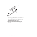
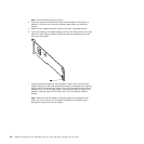
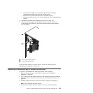
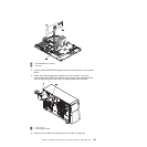
3. Rotate the power-supply cage assembly out of the chassis. Lift up the
power-supply cage handle and pull the power-supply cage assembly all the
way up until the retainer latch locks the cage in place on the chassis.
Chapter 5. Installing optional devices and replacing customer replaceable units 101