


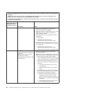

Table 2. System-board jumpers (continued)
Jumper number Jumper name Jumper setting
JP6 UEFI boot recovery jumper
v Pins 1 and 2: Normal
(default) - Loads the
primary server firmware
ROM.
v Pins 2 and 3: This enables
the server to recovery if
the server firmware
becomes damaged.
Notes:
v If no jumper is present, the server responds as if the pins are set to 1 and 2.
v Do not change the jumper pin position after the server is turned on. Changing the
position of the UEFI boot recovery jumper from pins 1 and 2 to pins 2 and 3 before the
server is turned on alters which flash ROM page is loaded. This can cause an
unpredictable problem.
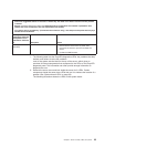
The following table describes the function of each pin on the SW6 switch block.
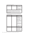
Table 3. System-board switches
Switch pin number Default value Description
1 Off Reserved.
2 Off Power-on password override.
Changing the position of this
switch bypasses the
power-on password check
the next time the server is
turned on and starts the
Setup Utility so that you can
change or delete the
power-on password. You do
not have to move the switch
back to the default position
after the power-on password
is overridden.
Changing the position of this
switch does not affect the
administrator password check
if an administrator password
is set.
See “Passwords” on page
141 for additional information
about passwords.
3 Off Reserved.
4Off
v When this switch is on Off,
this is normal mode. This
loads the primary IMM
firmware ROM page.
v When this switch is
toggled to On, this loads
the secondary (backup)
IMM firmware ROM page.
32 ThinkServer TD200 Types 3724, 3808, 3809, 3815, 3817, 3824, 3826, 3836: Installation and User Guide