


D8B Manual • Chapter 2 • page 23
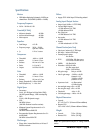
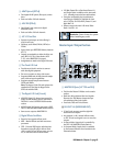
3 ADAT Optical (OPT•8)
• Two digital ADAT optical (fiber optic) connec-
tions.
• Each card offers I/O for 8 channels.
4 AES/EBU (PDI•8)
• One 25-pin D-sub connector in digital
AES/EBU format.
• Each card offers I/O for 8 channels.
5 ALT I/O Card Slot
• Separate input/output card slot offering 8
more ins and outs.
• Holds any card: AIO•8, DIO•8, OPT•8, or
PDI•8.
• Inputs show up at RETURNS faders (channels
65–72).
• Outputs are assignable to either the 8 bus out-
puts (BUS 1–8), the 12 Aux Sends (AUX
1–12), or the MASTER L-R outputs.
• Assignments are made in the Digital I/O menu.
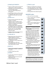
6 The Clock I/O Card
• Provides word clock in and out to connect
with other digital equipment.
• For use as a master or slave clock source.
• Supports 48kHz and 44.1kHz internal sample
rates, with vari-speed capabilities.
• Supports external sample rates between
32kHz and 50kHz.
Note: The Apogee Clock I/O card replaces the
standard clock card that is shipped in the
SYNC slot with the D8B.
7 The Digital I/O Card (2-track)
• AES/EBU digital I/O. Stereo interconnect for
master record machine. Input is connected to
DIGITAL 1 in the CONTROL ROOM monitor
section.
• S/PDIF digital I/O. Input is connected to DIGI-
TAL 2 in the CONTROL ROOM monitor section.
• Same source output as MASTER L-R.
8 Digital Effects Card Slots
• Room for four separate effects cards.
• MFX – Mackie Effects card with two stereo
processors.
• UFX – Universal DSP engine with functions
dependent on specific plug-in effects. Each
card is capable of four discrete mono, two ste-
reo, or one stereo and two mono effects.
• L-R Mix, Channel Pre or Post Insert, Buses 1-8,
and Plugin Chain, in addition to the Aux sends
1–12, internally route to the four card locations.
• Using the configurable plug-in architecture,
insert plug-in capability is available for chan-
nels 1–48 (Pre- and Post-DSP), Buses 1-8, and
Main Mix L-R.
• Effects return to the main L-R mix at Fader
Bank 3 via FX 1–16.
Reminder: Power down the system
before installing any cards!
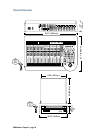
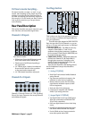
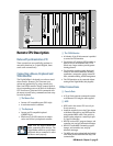
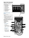
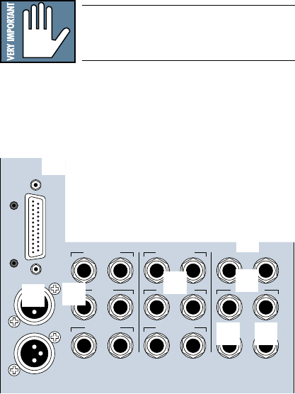
Master Input/Output Section
TALKBACK
PHONES 2
PUNCH I/O
PHONES 12 TRACK IN A
MASTER OUT
2 TRACK IN B
STUDIO OUT
2 TRACK IN C
MASTER OUT
LR
L
R
CR
MAIN
BUS OUT 1-8
&
SURROUND OUT
CR
NEAR FIELD
LR
LR
LR
LR
LR
LR
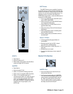
9 MASTER OUTputs (1/4" TRS and XLR)
• Fed from the Master L/R fader on the console
surface.
• Both sets deliver balanced line-level signals.
However, the TRS Master Outputs also pro-
vide unbalanced line-level signals.
• Post fader, DSP, and D/A converter.
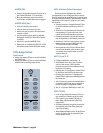
bl BUS OUT 1–8 (SURROUND OUT)
• 25-pin D-sub connector provides eight bal-
anced line-level outputs.
• Any channel (1–48), internal effects return,
or ALT IN can be assigned to one or more bus
outputs.
• In Stereo Mode: Output level is controlled by
the BUS 1–8 MASTERS (Fader Bank 4).
• In Surround Mode: Output level is controlled
by the Surround Monitor Level controls in the
Surround window.
9
bl
bm
bn
bo
bp bq
br