


D8B Manual • Chapter 3 • page 88
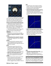
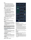
RATIO
• Determines the change in output level as a
function of the change in input level, once the
signal level drops below the threshold. This is
sometimes called downward expansion. The ratio
control ranges from 1:1.0 to 1:inf. Thus, if the ratio
is 1:2, a decrease in input level of 10 dB results in
a 20 dB decrease in output level (assuming the
input is below the threshold level).
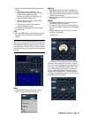
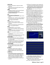
MIDI
• Enables external MIDI triggering for the gate.
• This can be useful for gating drums based on a
sequenced MIDI drum pattern.
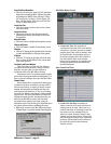
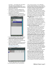
• To set up MIDI gate triggering:
1. Select MIDI Map from the Windows menu.
2. Select New MIDI Route from the Edit window.
3. Assign a MIDI note by selecting Note from the
MIDI Status drop-down menu.
4. Select Gate MIDI Trigger from the Parameter
column.
5. Send a MIDI note to the D8B from a sequencer or
other MIDI device. The Mode setting in the MIDI
Map determines when the gate opens and closes
(see “Creating a Route” on page 94).
• Gate MIDI Enable can also be turned on and off
via external MIDI note commands.
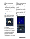
ACTIVE
• Click the ACTIVE button to turn on the gate for
the selected channel.
MENU
• Click the MENU button to Open, Save, Reset,
Undo, Cut, Copy, and Paste a Gate patch.
MEM A/B
• Each MEMory stores the most recent MEM A or
MEM B EQ settings made for the selected channel.
• Click either of these memory positions to instantly
recall the stored settings.
• Ideal for making quick A/B comparisons between
gate settings.
Note: Meter View and Meter Mode are not stored in
the MEM A or MEM B settings.
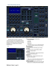
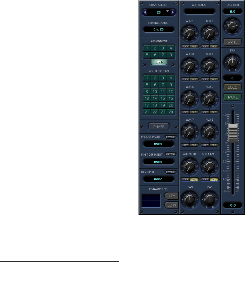
Additional Fat Channel Controls
CHANNEL SELECT
• Use the arrows on either side of the channel number
(or the arrow keys on the keyboard) to scroll up or
down through the D8B channels.
• Click in the “Chan. Select” window for a pull-down
of all the channels.
CHANNEL NAME
• This displays the channel name.
• Double-click on the name to highlight it, then type in
the new channel name (up to 16 characters). Press
Enter or click elsewhere to complete the operation.
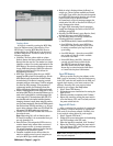
ASSIGNMENT
• Assign the channel to the main L/R bus or any of
the 8 bus outputs.
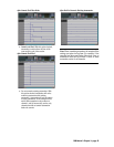
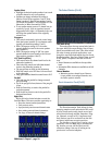
ROUTE TO TAPE
• Assign the channel to a tape output.
• Highlight the desired numbers to send the channel
to one or many tape outputs.
• This is the most visual way to tell if a channel is
routed to several tape outputs.
• A channel can be assigned to more than one tape
out, but only the last one selected appears in the
channel’s OUT window (in the overview screen).
• No two channels can be assigned to the same tape
output. To sum channels to a tape output, assign
them to a bus, the route the bus to a tape out.
Phase
• Highlight PHASE to invert the channel polarity by
180 degrees.
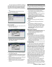
Aux Sends
• Use the on-screen knobs to adjust any of the aux
send levels.
• Press Control while clicking the Aux knob to set
Aux send level to unity gain.
• Click the PRE button directly below the Aux send
knob to toggle the individual Aux Pre/Post status.
• Click the OFF button directly below the Aux send
knob to toggle the individual channel Aux on and
off (mute).