D8B Manual • Chapter 2 • page 25
PARALLEL
MOUSE
CONCEIVED, DESIGNED, AND MANUFACTURED BY MACKIE DESIGNS INC • WOODINVILLE • WA • USA • MADE IN USA • FABRIQUE AU USA • COPYRIGHT ©1997 •
THE FOLLOWING ARE TRADEMARKS OR REGISTERED TRADEMARKS OF MACKIE DESIGN INC.: "MACKIE", "DIGITAL SYSTEMS", D8B AND THE "RUNNING MAN" FIGURE •
CONSOLE DATA
KEYBOARD
Remote CPU Description
Data and Synchronization I/O
These connections are specifically pertinent to
non-audio functions (or, in plain English, these
aren’t audio connections!).
Connecting a Mouse, Keyboard and
SVGA Monitor
The Digital 8•Bus is designed to work as a stand-
alone console. However, you’ll increase your
options and productivity by using a mouse, key-
board, and SVGA monitor. Simply connect them to
the corresponding ports on the back of the Remote
CPU for access to point-and-click commands with
the mouse, as well as key commands and text entry
from the keyboard.
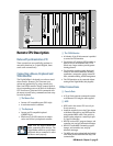
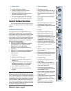
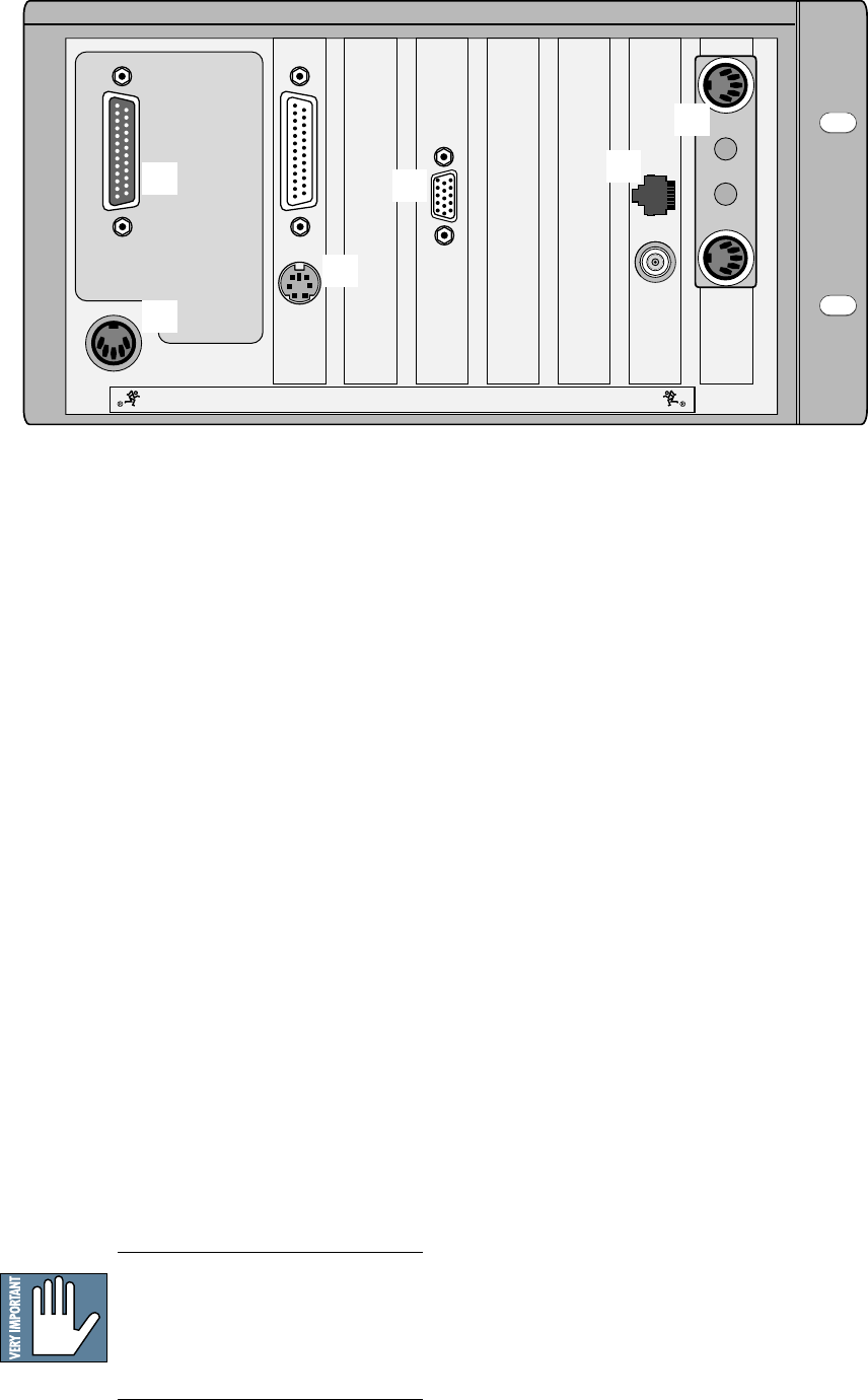
1 The Mouse Port
• Connect a PC-compatible mouse (PS/2 style).
• A two-button mouse is sufficient.
2 The Keyboard
• Connect any PC-compatible keyboard
(QWERTY style).
• Must have a 5-pin DIN connector. An adapter
can be used for the 9-pin keyboard connector.
Note: Turn the Digital 8•Bus OFF
before connecting these devices. The
Digital 8•Bus must boot up with these
peripheral devices connected in order
for them to work properly.
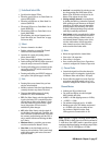
3 The SVGA Monitor
• A hi-density 15-pin D-Sub connector is provided
to connect an SVGA monitor.
• Use at least a 17" multisync SVGA monitor ca-
pable of 1024 X 768 resolution and a 72Hz
refresh rate. Larger monitors provide greater
viewing pleasure.
• Use of monitor provides graphic display and
control of most console functions, including
equalization, compression, gating, internal ef-
fects, automation editing, and file management.
• The SVGA monitor can be connected without
turning off the Digital 8•Bus (hot-plugable).
Other Connections
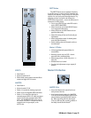
4 Console Data
• A 25-pin D-sub connector connects the console
to the Remote CPU using the cable supplied.
5 MIDI
• MIDI card in the remote CPU uses a 9-pin
D-sub connector.
• Install the supplied 9-pin to dual 5-pin adapter
to facilitate connection to your MIDI network
using standard MIDI cables. This could be a
plastic housing adapter or a rattail 9-pin split
to 5-pin I/O connection.
• MIDI IN receives MTC, program changes, and
controller, note, and poly aftertouch messages.
• MIDI OUT sends MMC commands, program
changes, and controller, note, and poly
aftertouch messages.
• The MIDI card can be replaced with the Serial•9
card, which provides both MIDI and Sony 9-Pin
communication.
1
2
3
5
4
6


