


Installation and User Manual
Figures
figure description . . . . . . . . . . . . . . . . . . . . . . . . . . . . . . . . . . . . . . . . . . . . . . . . .page
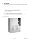
1-1: Galaxy PW™ System. . . . . . . . . . . . . . . . . . . . . . . . . . . . . . . . . . . . . . . .1 — 2
1-2: Galaxy PW™ Single UPS System. . . . . . . . . . . . . . . . . . . . . . . . . . . . . .1 — 4
1-3: Fuse Curve Chart. . . . . . . . . . . . . . . . . . . . . . . . . . . . . . . . . . . . . . . . . . .1 — 7
2-1: Handling Cabinet From the Bottom or Rolling on Bars. . . . . . . . . . . . . . .2 — 3
2-2: Dismantling Leg Supports and Attaching Spacers to Cabinet. . . . . . . . .2 — 4
2-3: Layout of the Major Cabinet Components. . . . . . . . . . . . . . . . . . . . . . . .2 — 5
2-4: Component Layout in a Battery Cabinet or a
Battery Circuit-breaker Enclosure. . . . . . . . . . . . . . . . . . . . . . . . . . . . . .2 — 6
2-5: 350A and 1200A Maintenance Bypass Cabinet. . . . . . . . . . . . . . . . . . . .2 — 7
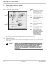
2-6: Control Panel Indicators. . . . . . . . . . . . . . . . . . . . . . . . . . . . . . . . . . . . . .2 — 8
2-7: Single UPS Unit Start-up Diagram. . . . . . . . . . . . . . . . . . . . . . . . . . . . .2 — 10
2-9: Parallel UPS Unit for Increased Output. . . . . . . . . . . . . . . . . . . . . . . . . .2 — 11
3-1: Galaxy PW™ Single UPS Unit Wire Diagram. . . . . . . . . . . . . . . . . . . . . .3 — 2
3-2: Single UPS Unit Power Circuit Connections. . . . . . . . . . . . . . . . . . . . . . .3 — 2
3-3: Parallel UPS Unit Power Circuit Diagram. . . . . . . . . . . . . . . . . . . . . . . . .3 — 3
3-4: Connections Between UPOZ Boards. . . . . . . . . . . . . . . . . . . . . . . . . . . .3 — 4
3-5: Two Parallel UPS Units Connections. . . . . . . . . . . . . . . . . . . . . . . . . . . .3 — 5
3-6: Three Parallel UPS Units Connections. . . . . . . . . . . . . . . . . . . . . . . . . . .3 — 6
3-7: Four Parallel UPS Units Connections. . . . . . . . . . . . . . . . . . . . . . . . . . . .3 — 6
3-8: Standard Auxiliary Circuits Connections. . . . . . . . . . . . . . . . . . . . . . . . . .3 — 9
3-9: Installing the "Temperature Monitor" in a Battery Cabinet. . . . . . . . . . .3 — 10
3-10: Temperature Monitor" Base. . . . . . . . . . . . . . . . . . . . . . . . . . . . . . . . . . .3 — 11
3-11: Single UPS Unit Connection of the Battery "Temperature Monitor". . . .3 — 12
3-12: Connection of the Battery "Temperature Monitor."
(In Parallel UPS Units with Batteries in Same Room.) . . . . . . . . . . . . .3 — 13
3-13: Connection to the "Media Contacts 11" Board. . . . . . . . . . . . . . . . . . . .3 — 14
4-1: Control Panel and Circuit Breaker Diagram. . . . . . . . . . . . . . . . . . . . . . .4 — 1
4-2: Single UPS Diagram . . . . . . . . . . . . . . . . . . . . . . . . . . . . . . . . . . . . . . . .4 — 2
4-3: Parallel UPS Two Parallel Connected UPS Units. . . . . . . . . . . . . . . . . . .4 — 2
4-4: Parallel UPS Two to Four Parallel Connected UPS Units. . . . . . . . . . . .4 — 2
4-5: Normal Operation Indicator Diagram. . . . . . . . . . . . . . . . . . . . . . . . . . . .4 — 3
4-6: Normal AC Source Indicator Diagram. . . . . . . . . . . . . . . . . . . . . . . . . . . .4 — 4
4-7: Normal Operation Mode Indicator Diagram. . . . . . . . . . . . . . . . . . . . . . .4 — 5
4-8: Battery Charge Cycle Chart. . . . . . . . . . . . . . . . . . . . . . . . . . . . . . . . . . .4 — 6
4-9: Installation with an Engine Generator Set. . . . . . . . . . . . . . . . . . . . . . . . .4 — 6
4-10: Operating in On-line Mode Diagram. . . . . . . . . . . . . . . . . . . . . . . . . . . . .4 — 7
4-11: Overload Curve Diagram. . . . . . . . . . . . . . . . . . . . . . . . . . . . . . . . . . . . . .4 — 9
4-12: Measurement System Diagram. . . . . . . . . . . . . . . . . . . . . . . . . . . . . . . .4 — 11
4-13: Display of Alarm Messages.. . . . . . . . . . . . . . . . . . . . . . . . . . . . . . . . . .4 — 16
5-1: UPS Isolation Diagram for Normal AC Bypass Source. . . . . . . . . . . . . . .5 — 3
5-2: Panel Procedures for UPS Isolation. . . . . . . . . . . . . . . . . . . . . . . . . . . . .5 — 3
5-3: Start-up After Isolation Procedure is Completed. . . . . . . . . . . . . . . . . . . .5 — 3
5-4: Isolate All UPS’s Procedures Diagram. . . . . . . . . . . . . . . . . . . . . . . . . . .5 — 4
Contents c v86-133060-00 A00