


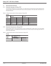
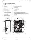
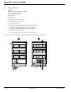
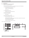

2.4 Battery Cabinet
Legend:
AA: cross-sectional view of the cabinet,
B: front view of the cabinet,
C: front panel,
D: rear panel,
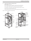
E: cable ties to duckboard shelf,
F: cable exit through the bottom,
G: trough, if applicable,
H: connection of exposed conductive parts to duckboard shelf,
I: cable exit to battery connection point in UPS cabinet,
J: cable exit to an additional battery cabinet, if applicable,
K: cable ties to duckboard shelf,
L: fixture locking circuit breaker "QF1" in the open position.
Figure 2-4: Component Layout in a Battery Cabinet or a Battery Circuit-breaker Enclosure.
Galaxy PW™ UPS 100 to 225kVA
System Setup2 — 6 86-133060-00 A00
XR1
QF1
+
+
D
C
A
A
LK
I
J
F
G
E
H
BAA