


Installation and User Manual
Operation 4 — 1186-133060-00 A00
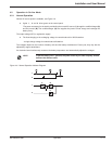
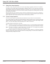
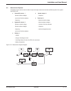
4.8 Measurement System
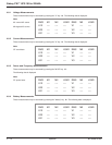
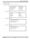
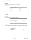
The display may be used to read a number of input and output measurements made at different points in the system.
See Figure 4-12.
◗ Normal AC source 1 ◗ Inverter output 4
- phase-to-phase voltages, - frequency
- currents of the three phases,
◗ Total load 6
- frequency. - phase-to-neutral voltage.
◗ Bypass AC source 2 - phase-to-phase voltages.
- phase-to-neutral voltage, - currents of the three phases.
- phase-to-phase voltages, - frequency.
- frequency, - active and apparent power.
- currents of the three phases.
◗ Battery 3
- voltage.
- charge or discharge current.
- remaining battery time (for the UPS unit concerned).
- battery temperature.
Figure 4-12: Measurement System Diagram.
1
2
Q1
Q5N
QF1
U - V - I - F
U - I - F
U - I
F
U - V - I - F - P
AB
C
D
Q4S
6431
2