


Operation
4.0 Scope
Operation describes the start-up for single and parallel units, modes of operation, normal specifications for operating
the Galaxy PW™ 100 to 225kVA, including display messages, measurement systems, alarms, batteries, and log
time stamping operations.
WARNING Rectifier/charger start-up is automatic when normal AC input circuit breaker Q1
is closed. DC voltage is present in the DC bus.
4.1 Start-up of a Module
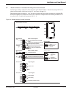
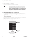
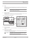
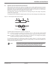
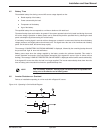
Rectifier/charger start-up is automatic when the normal AC input circuit breaker Q1 is closed. The green
"rectifier/charger" light 1 on the control panel goes on. Close battery circuit breaker QF1.
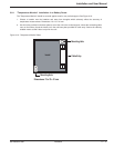
Figure 4-1: Control Panel and Circuit Breaker Diagram.
4.1.1 Start-up of an Inverter
When the rectifier/charger is on, press the "inverter ON" button 7 on the control panel. The green "inverter" light
4 flashes.
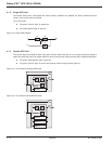
4.1.2 Emergency Power Off (EPO)
The UPS emergency shutdown function is generally wired to a "mushroom-head" type emergency-off pushbutton.
In case of its use, the pushbutton contact has to reset.
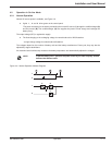
IMPORTANT After EPO/REPO, unit has to be reset by opening M2 feed (switch Q4S). Open
switch Q5N also, and then follow the procedure of single UPS for single unit or
parallel UPS for parallel units to start-up the system.
1
2
VA
W. Hz
fault
18
17
8
7
643 521
22
2119 20
16
9 10 11 12 13 1514 15
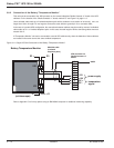
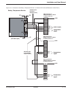
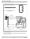
maintenance bypass:
Q3BP
inverter (B):
DC to AC
power
isolation:
Q4S
isolation and
protection:
Q5N
rectifier/
charger (A):
AC to DC
power
QF1: isolation
and protection
normal
AC
input
battery (D):
backup power
static bypass (C):
bypass
AC
input
Q1
isolation
and
protection
(1)
(2)
harmonic
fliter
*FUSE
*FUSE
Operation 4 — 186-133060-00 A00