


Installation and User Manual
Start-up
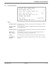
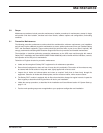
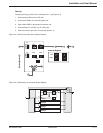
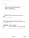
Following servicing, proceed in the following order: (See Figure 5-3)
1. Close switch Q1, then after approximately ten seconds, switches QF1, Q5N and Q4S,
2. 0pen bypass switch Q3BP,
3. Start the inverter (press the "inverter ON" button 7 ).
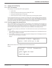
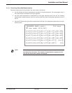
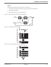
Figure 5-1: UPS Isolation Diagram for Normal AC Bypass Source.
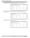
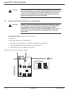
Figure 5-2: Panel Procedures for UPS Isolation.
Figure 5-3: Start-up After Isolation Procedure is Completed.
FF
1
0
1
0
1
0
1
0
Q5NQ1 Q4S
3
1
2
Q3BP
1
0
5
4
6
1
0
1
0
1
0
1
0
1
0
1
0
1
0
QF1
0
I
1
0
1
0
1
0
1
0
1
0
1
0
1
0
1
0
1
0
1
0
1
0
1
0
1
0
Q5NQ1 Q4S
3
1
2
1
0
Q3BP
1
0
1
0
5
4
6
QF1
0
I
1
0
1
0
1
0
1
0
7
8
Q1
Q5N
QF1
Q3BP
Q4S
AB
C
D
1
2
Maintenance 5 — 386-133060-00 A00