


3 — 186-133060-00 A00
Installation
3.0 Scope
Installation guides the User through single and parallel UPS unit power cable connections, hot swap options,
connections between cabinets, communication card connections, battery ‘temperature monitoring’ installation. Wire
diagrams are included for configuring the unit to specifications.
MGE recommends obtaining an MGE field service engineer for final installation and basic startup for single and
parallel units. Final installation and start-up should be completed and performed by a qualified MGE Field
Service Engineer.
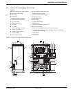
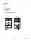
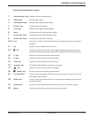
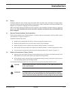
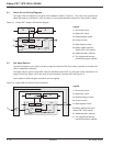
3.1 Optional Communications Card Installation
Three slots are available on the "Media Contacts 11" board for optional communications. See the position of these
slots marked "P" in Figure 2-3, page 2—5.
Installation of Boards setup notes:
◗ Boards may be installed with the UPS on, without removing the protective covers.
◗ Boards must be pushed to the end of the slots to ensure correct installation.
◗ Board front plates must be screwed to the protective "Media Contacts 11" board cover.
◗ Wire routing holes are provided in the support for the "Media Contacts 11" board for tying down the wires;
◗ The control wires must then be routed through the cableway marked "W" in figure 2-3, page 2—5.
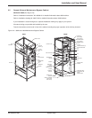
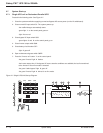
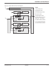
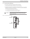
3.2 Notes on Connection of Power Circuits
◗ Open the doors and remove the lower terminal shields (secured by screws to the cabinet chassis) of the
UPS cabinets, connect the power cables, each cabinet must be grounded.
◗ All the cabinets must be interconnected for equipotential bonding, forming a mesh which is itself connect-
ed to the building structure and earthing electrode.
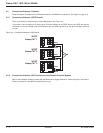
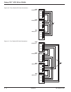
The connection drawings hereafter show the cabinets with doors open and terminal shields removed.
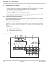
CAUTION Before making connections, check that switches Q1, Q4S, Q3BP, Q5N and QF1 are
in the "open" position.
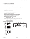
IMPORTANT For parallel UPS with an external bypass unit, the power connections between
each UPS cabinet and the external bypass unit must imperatively be of the same
length. Outside the cabinets, separate the auxiliary wiring from the power cables.
Installation