


Installation and User Manual
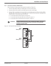
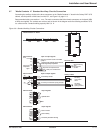
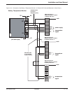
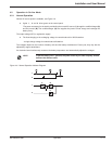
Figure 3-12: Connection of the Battery "Temperature Monitor." (In Parallel UPS Units with Batteries in Same Room.)
+12
(unit shown open)
XR2
XR1
-12
DC-
DC +
12
11
10
9
8
7
6
5
4
3
2
1
power supply
XR2 connector on
'Media Contacts 11' Board
in Galaxy PW unit 1:
temperature
signal
-12V
+12V
each
DC +
DC -
Shielded cable
(2 twisted
telephone pairs)
Battery Temperature Monitor
12
11
10
9
8
7
6
5
4
3
2
1
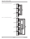
XR2 connector on
'Media Contacts 11' Board
in Galaxy PW unit 2:
temperature
signal
each
DC +
DC -
12
11
10
9
8
7
6
5
4
3
2
1
XR2 connector on
'Media Contacts 11' Board
in Galaxy PW unit n:
temperature
signal
each
DC +
DC -
Shielded cable
(1 or 2 twisted
telephone pairs)
Installation 3 — 1386-133060-00 A00