


Installation and User Manual
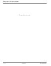
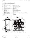
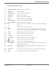
2.3 Galaxy PW™ Cabinet Major Components
Legend:
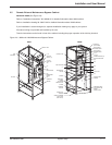
AA: cross-sectional view of the cabinet,
B: front view of the cabinet,
C: front panel,
D: rear panel,
1: normal AC input connection,
2: bypass AC input connection,
E: load connection,
F: battery connection,
G: air inlets,
H: air outlets,
I: cable exit through the bottom,
J: trough, if applicable,
K: rectifier/charger module,
L: inverter module,
M: static-bypass module,
Figure 2-3: Layout of the Major Cabinet Components.
System Setup 2 — 586-133060-00 A00
H
G
G
H
F
E
1
P
2
G
Y
Q1
Q4S
Q5NQ3BP
L1
L2
L3
L1L2L3
L1
L2
L3
GND
N
M
Q
Z
S
L
A
B
M
N 3
T
W
U
R
A
X
J
I
1, 2, E,F
D
C
AA
K
O
V
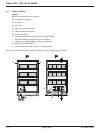
N: rack containing electronic boards,
O: Media Contacts 11 board,
P: slot for communications boards,
Q: FUE input fuses,
R: FUS output fuses,
S: RALI board,
T: UPOZ /UCOZ board,
U: MUSI board,
V: backfeed protection (contactor),
W: control wire routing,
X: fuses for overvoltage protection RC circuit on bypass,
Y: control-wire connection (auxiliary "Media Contacts 11" circuits and
communications options).
z: EP0I Board
3: VETI Board