


Installation and User Manual
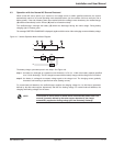
The shutdown of one inverter results in overload on the other inverters in operation. Two cases may then arise:
A) if the overload on each remaining inverter is > than 1.65 in, the load is immediately transferred to the bypass
AC source.
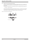
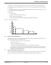
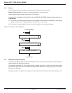
B) if the overload is less than 1.65 in, the remaining inverters support the overload (see curve in Figure 4-11), and
the load is transferred to the bypass AC source.
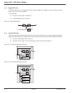
After this transfer:
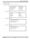
- the light 4 goes off,
- the buzzer is activated and sounds continuously,
- the light 3 goes on and turns green,
- the message "LOAD NOT PROTECTED, PARALLEL ON-LINE MODE" is displayed.
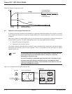
Figure 4-11: Overload Curve Diagram.
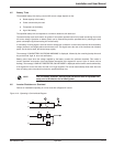
4.6.3 Parallel UPS With Redundancy
The shutdown of one UPS unit is of no consequence for the load. The others each take up an equal amount of load
power and the load continues to be supplied normally.
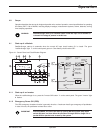
◗ Unit shutdown results in the following on the control panel:
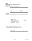
- Lights 4 and 5 go off,
- Activation of the buzzer (continuous beep),
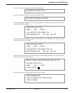
- The message "LOAD NOT PROTECTED, PARALLEL ON-LINE MODE" is displayed.
- In the event of an overload, the system only loses its redundancy as long as the overload is less than the
total rated power of the functioning units. If the overload is greater, the operating mode is that previously
described for systems without redundancy.
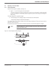
4.7 Output Voltage Quality and Continuity
The output voltage is stable in amplitude and frequency and is free of interruptions or transients outside specified
tolerances, irrespective of normal AC source or load disturbances (outages, load step changes, etc.).
I
12345678910
(min)
1,5 In
1,35 In
1,25 In
1,15 In
1,10 In
1,05 In
In
t
30 120
Operation 4 — 986-133060-00 A00