


Installation and User Manual
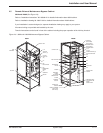
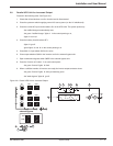
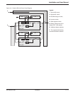
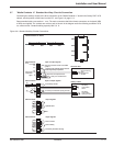
Figure 3-3: Parallel UPS Unit Power Circuit Diagram.
Legend:
1: Normal AC source,
2: Bypass AC source,
A: Rectifier/charger module,
B: Inverter module,
C: Static-bypass module,
D: Battery cabinet next to the
Galaxy PW™ UPS cabinet,
E: Additional battery cabinets,
F: The equipotential-bonding
connection between cabinets.
Installation 3 — 386-133060-00 A00
Galaxy PW
2
1
D
+
–
+
–
E
F
QF1
F
2
1
D
+
–
+
–
E
F
QF1
F
Galaxy PW
2
Q3BP
Q5N
2
C
B
A
Q4S
Q1 Q5N
( )
( )
C
B
A
Q4S
Q1 Q5N
( )
( )
( )