


Galaxy PW™ UPS 100 to 225kVA
Contentsc ii 86-133060-00 A00
Section 2 System Setup (continued)
section description . . . . . . . . . . . . . . . . . . . . . . . . . . . . . . . . . . . . . . . . . . .page
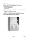
2.3 Galaxy PW™ Cabinet Major Components . . . . . . . . . . . . . . . . . .2 — 5
2.4 Battery Cabinet . . . . . . . . . . . . . . . . . . . . . . . . . . . . . . . . . . . . . . .2 — 6
2.5 Remote External Maintenance Bypass Cabinet . . . . . . . . . . . . . .2 — 7
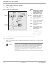
2.6 General Instructions for Screens . . . . . . . . . . . . . . . . . . . . . . . . .2 — 8
2.6.1 Control Panel Indicators and Definitions . . . . . . . . . . . . . . . . . . .2 — 8
2.7 System Start-up . . . . . . . . . . . . . . . . . . . . . . . . . . . . . . . . . . . . .2 — 10
2.7.1 Single UPS unit or Redundant Parallel UPS . . . . . . . . . . . . . . .2 — 10
2.8 Parallel UPS Unit for Increased Output . . . . . . . . . . . . . . . . . . .2 — 11
Section 3 Installation
3.0 Scope . . . . . . . . . . . . . . . . . . . . . . . . . . . . . . . . . . . . . . . . . . . . . .3 — 1
3.1 Optional Communications Card Installation . . . . . . . . . . . . . . . . .3 — 1
3.2 Notes on Connection of Power Circuits . . . . . . . . . . . . . . . . . . . .3 — 1
3.3 Power-Circuit Wiring Diagrams . . . . . . . . . . . . . . . . . . . . . . . . . .3 — 2
3.4 Hot Swap Options . . . . . . . . . . . . . . . . . . . . . . . . . . . . . . . . . . . . .3 — 2
3.5 Connections Between Cabinets . . . . . . . . . . . . . . . . . . . . . . . . . .3 — 4
3.5.1 Connections Between UPOZ Boards . . . . . . . . . . . . . . . . . . . . . .3 — 4
3.5.2 Connections Between UPS Cabinets and the
Remote External Bypass . . . . . . . . . . . . . . . . . . . . . . . . . . . . . . .3 — 4
3.5.3 Connections Between MUSI Boards . . . . . . . . . . . . . . . . . . . . . .3 — 5
3.6 Environmental Signal of the Media Contacts 11 Board . . . . . . . .3 — 7
3.6.1 Signal Reception . . . . . . . . . . . . . . . . . . . . . . . . . . . . . . . . . . . . .3 — 7
3.6.2 Signal Transmission . . . . . . . . . . . . . . . . . . . . . . . . . . . . . . . . . . .3 — 7
3.7 "Media Contacts 11" Standard Auxiliary Circuits Connection . . . .3 — 9
3.7.1 Battery Circuit Breaker "QF1" Connection . . . . . . . . . . . . . . . . .3 — 10
3.8 Installation of the "Temperature Monitor" in the
Battery Cabinet . . . . . . . . . . . . . . . . . . . . . . . . . . . . . . . . . . . . . .3 — 10
3.8.1 "Temperature Monitor" installation in a Battery Room . . . . . . . .3 — 11
3.8.2 Connection of the Battery "Temperature Monitor" . . . . . . . . . . .3 — 12
3.9 About Final Installation Steps . . . . . . . . . . . . . . . . . . . . . . . . . . .3 — 14
Section 4 Operation
4.0 Scope . . . . . . . . . . . . . . . . . . . . . . . . . . . . . . . . . . . . . . . . . . . . . .4 — 1
4.1 Start-up of a Module . . . . . . . . . . . . . . . . . . . . . . . . . . . . . . . . . . .4 — 1
4.1.1 Start-up of an Inverter . . . . . . . . . . . . . . . . . . . . . . . . . . . . . . . . .4 — 1
4.1.2 Emergency Power Off . . . . . . . . . . . . . . . . . . . . . . . . . . . . . . . . .4 — 1
4.1.3 Single UPS Unit . . . . . . . . . . . . . . . . . . . . . . . . . . . . . . . . . . . . . .4 — 2
4.1.4 Parallel UPS Unit . . . . . . . . . . . . . . . . . . . . . . . . . . . . . . . . . . . . .4 — 2
4.2 Operation in On-line Mode . . . . . . . . . . . . . . . . . . . . . . . . . . . . . .4 — 3
4.2.1 Normal Operation . . . . . . . . . . . . . . . . . . . . . . . . . . . . . . . . . . . . .4 — 3
4.2.2 Operation with the Normal AC Source Down . . . . . . . . . . . . . . . .4 — 4
4.3 Operation with the Normal AC Source Restored . . . . . . . . . . . . .4 — 5