


Installation and User Manual
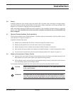
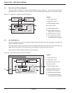
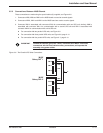
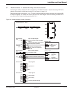
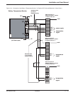
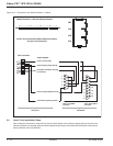
3.7 "Media Contacts 11" Standard Auxiliary Circuits Connection
Connecting the auxiliary circuits to the three connectors on the "Media Contacts 11" board in the Galaxy PW™ UPS
cabinet, see the position of this board, marked "O", see Figure 2-3, page 2—5.
Recommended cable cross-section: 1 mm
2
. The male connectors that fit the female connectors on the board (XR2
to XR5) are supplied. The contacts are volt-free and are shown in the diagram under the following conditions: UPS
on, contact at rest. Contact breaking capacity: 250 V, 5 A.
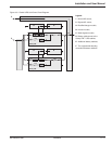
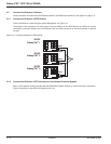
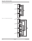
Figure 3-8: Standard Auxiliary Circuits Connections.
Installation 3 — 986-133060-00 A00
Media Contacts 11 Board
12
11
10
9
8
7
6
5
4
3
2
1
10
9
8
7
6
5
4
3
2
1
-12V
-12V
24V CC
-12V
XR3 connector
AC
AC
AC
power supply
input or output signals:
input or output signals:
emergency shutdown breaker circuit REPO
(jumper Y
XR2 connector
harmonic filter
battery cubicle
XA13 terminal block
correction with optional electric boad for
measuring battery temperature
temperature
signal
OF1 battery circuit-breaker opening command
harmoni
cs over-temperature fault
battery-room ventilation fault
-12V
+12V
QF1 battery
circuit breaker
closed
QF1 battery
circuit breaker
opening command
XA1 terminal block
output signals:
EPO
XR2 XR3 XR4 XR5
12 - - - - - - - - - -1 10 - - - - - - - -1 10 - - - - - - - -1 10 - - - - - - - -1
circuit
thermal measuring
of the
harmoinc-filter
circulator
10
9
8
7
6
5
4
3
2
1
XR4 connector
output signals:
load or battery
10
9
8
7
6
5
4
3
2
1
XR4 connector
low-battery shutdown warning
load or inverter
AC
AC
2
1
2
1
2
1
AC
Optional alarm
free auxilary contact
XR2
XR3
XR4
XR5
XR1
12 - - - - - - - - - -110- - - - - - - - - 1 10- - - - - - - - - 1 10- - - - - - - - - 1