


2.7 System Start-up
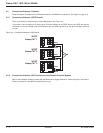
2.7.1 Single UPS unit or Redundant Parallel UPS
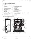
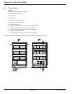
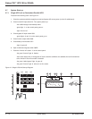
Proceed in the following order: See Figure 2-7.
1. Close the upstream switches supplying normal and bypass AC source power (on the LV switchboard).
2. Close normal AC input switch Q1. The system powers up:
- the rectifier/charger automatically starts.
- green light 1 on the control panel goes on.
- light 2 turns red.
3. Close bypass AC input switch Q4S:
- green lights 3 and 5 on the control panel go on.
4. Close inverter output switch Q5N.
5. Close battery circuit breaker QF1:
- light 2 goes off.
6. Open maintenance bypass switch Q3BP.
7. Press the "inverter on" button 7 on the control panel:
- the green "inverter" light 4 flashes.
- the inverter starts, then, if the bypass AC source transfer conditions are satisfied, the load is transferred
to the inverter if the on-line mode is selected.
- the green "static-bypass" light 3 goes off.
- the green "inverter" light 4 shines for on-line mode.
Figure 2-7: Single UPS Unit Start-up Diagram.
Q5NQ1 Q4S
QF1
0
I
3
1
2
1
0
1
0
1
0
1
0
1
0
Q3BP
1
0
1
0
1
0
1
0
1
0
1
0
1
0
5
4
6
1
0
1
0
1
0
1
0
7
8
1
2
8
7
643 521
22
Galaxy PW™ UPS 100 to 225kVA
System Setup2 — 10 86-133060-00 A00