


Installation and User Manual
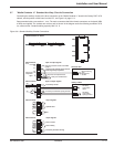
3.5.3 Connections Between MUSI Boards
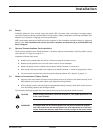
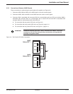
These connections are made using the special cables (A) supplied, see Figures 3-5.
1. Connectors XM5, XM6 and XM7 on the MUSI board are used to transmit signals.
2. Connectors XM10, XM11 and XM12 on the MUSI board are used to receive signals.
3. Connector XM5 is associated with connector XM10 for communication with one UPS unit; similarly, XM6 is
associated with connector XM11 for communication with a second UPS unit and XM7 is associated with
connector XM12 for communication with a third UPS unit.
◗ For connection with two parallel UPS units, see Figure 3-5.
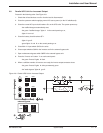
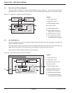
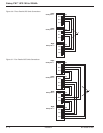
◗ For connection with three parallel UPS units, see Figure 3-6, page 3—6.
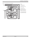
◗ For connection with four parallel UPS units, see Figure 3-7, page 3—6.
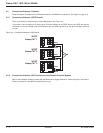
IMPORTANT Outside the cabinets, group the "UPOZ" inter-board and "MUSI" inter-board
connections with the inter-cabinet auxiliary connections, and separate this
assembly using power cables.
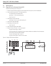
Figure 3-5: Two Parallel UPS Units Connections.
'MUSI'
Galaxy PW
TM
1
'MUSI'
Galaxy PW
TM
2
A
XM10
XM11
XM12
XM5
XM6
XM7
XM10
XM11
XM12
XM5
XM6
XM7
Installation 3 — 586-133060-00 A00