


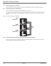
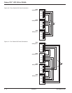
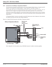
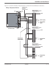
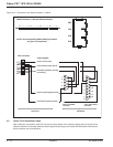

3.7.1 Battery Circuit Breaker "QF1" Connection
Connect the cable from connector XR3 (pins 2 to 8) on the "Media Contacts 11" board in the UPS cabinet to
connector XR1 in the battery cabinet containing battery circuit breaker QF1.
IMPORTANT
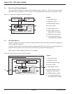
In the case of a complex installation with parallel units, there should be only one
emergency shutdown pushbutton and this pushbutton must interrupt all the units.
This pushbutton must therefore have as many contacts as there are units in the
installation. The emergency shutdown pushbutton turns off the rectifier/ chargers
and inverters, opens the battery circuit breakers (QF1), the input circuit breaker (Q1)
on the normal source, the backfeed protection contactor (K4S) on the bypass AC
source, blocks the static switches and activates a contact on the "Media Contacts 11"
board (terminals 1 to 3 on connector XR4).
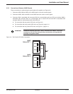
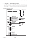
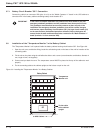
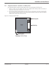
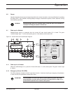
3.8 Installation of the "Temperature Monitor" in the Battery Cabinet
The "Temperature Monitor" unit is placed inside the battery cabinet housing circuit-breaker QF1. See Figure 3-9.
1. Open the unit cover, and before fixing, break the self-cleaving seal on the base of the unit for insertion of the
connecting cable.
2. Fix the unit on the plate using the self-adhesive sticker and a screw (nut and washer combination, diameter 4
mm, length 16 mm, not supplied).
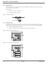
3. Connect and put back the cover. The temperature sensor MUST be placed at the top of the cabinet to work
properly.
4. Tie the connecting cable to the cabinet upright so that it does not pull on the unit.
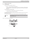
Figure 3-9: Installing the "Temperature Monitor" in a Battery Cabinet.
Battery Cabinet
Temperature
Monitor unit
Tie the cable
to the cabinet
upright
to UPS Cabinet
QF1
Galaxy PW™ UPS 100 to 225kVA
Installation3 — 10 86-133060-00 A00