


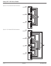
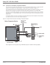
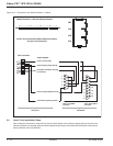
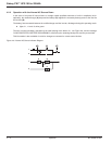

Figure 3-13: Connection to the "Media Contacts 11" Board.
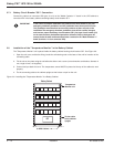
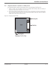
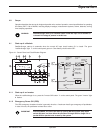
3.9 About Final Installation Steps
After making the connections, install the front and rear base plates of the cabinets, clipping them to the feet of the
cabinets (unless the connecting cables are fed through these openings), and refit the terminal shields of the terminal
blocks, switches and circuit breakers.
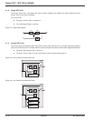
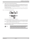
Media Contacts 11 Remote Indicators Board
XR2 XR3 XR4 XR5
12 - - - - - - - - - -1 10 - - - - - - - -1 10 - - - - - - - -1 10 - - - - - - - -1
XR2
XR3
XR4
XR5
XR1
12 - - - - - - - - - -110- - - - - - - - - 1 10- - - - - - - - - 1 10- - - - - - - - - 1
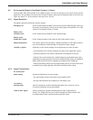
output signals:
load or battery (utility failure)
10
9
8
7
6
5
4
3
2
1
XR's connector
low-battery shutdown warning
(low battery)
load or inverter (ON)
load on bypass (bypass active)
commond W (system ground)
1
2
3
4
5
6
7
8
9
1
2
3
4
5
6
7
8
9
10
11
12
13
14
15
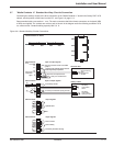
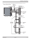
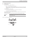
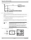
Galaxy PW
IBM AS400
male 9-pin SUB-D
connector
male 15-pin SUB-D
connector
NOTE: the corresponding IBM AS400 signal names
are given in parapharase.
Galaxy PW™ UPS 100 to 225kVA
Installation3 — 14 86-133060-00 A00