


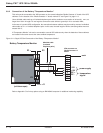
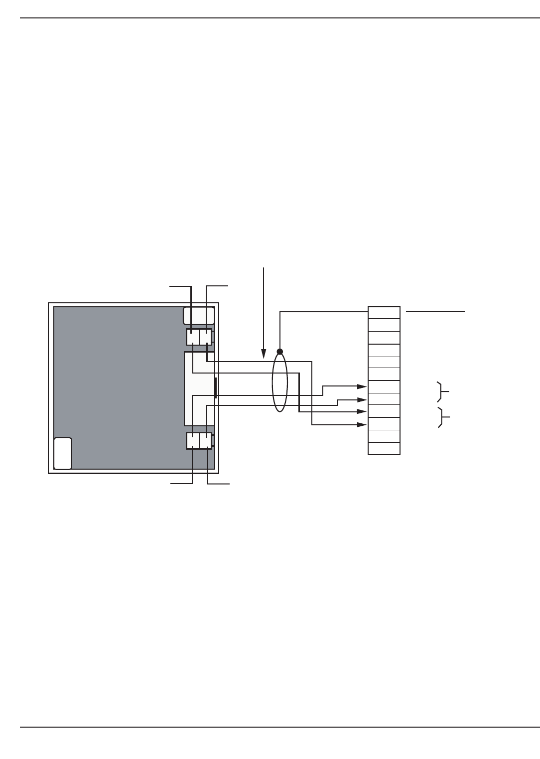
3.8.2 Connection of the Battery "Temperature Monitor"
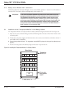
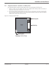
This unit must be connected to the XR2 connector on the remote indications "Media Contacts 11" board of the UPS
cabinets. For the location of the "Media Contacts 11" board, marked "O" see Figure 2-3, page 2—5.
Use a shielded cable made up of 2 twisted telephone pairs with a conductor cross-section of at least 0.1 mm
2
, not
longer than 100 m in length. Do not forget to connect the cable shield to ground pin 12 on connector XR2;
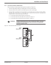
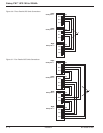
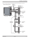
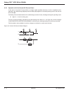
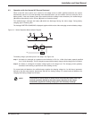
In the case of a parallel UPS configuration, the connections between cabinets may be made by means of a shielded
cable made up of 1 or 2 twisted telephone pairs. In this case, the total length of all the connecting cables must not
exceed 100 m;
A "Temperature Monitor" unit can be connected to several UPS cabinets only when the batteries of these cabinets
are located in the same room at the same ambient temperature.
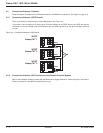
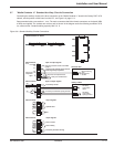
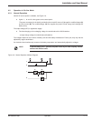
Figure 3-11: Single UPS Unit Connection of the Battery "Temperature Monitor".
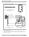
Refer to Appendix C for link-up options using an IBM AS400 computer for additional monitoring capability.
+12
(unit shown open)
XR2
XR1
-12
DC-
DC +
12
11
10
9
8
7
6
5
4
3
2
1
power supply
XR2 connector on
'Media Contacts 11'
Board:
temperature
signal
-12V
+12V
each
DC +
DC -
Shielded cable
(2 twisted
telephone pairs)
Battery Temperature Monitor
Galaxy PW™ UPS 100 to 225kVA
Installation3 — 12 86-133060-00 A00