


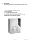

Installation and User Manual
1.6.2 Bypass AC Source
The parameters given in Table 1-2 and 1-2A can be used to determine the required rating of the upstream protec-
tive circuit breaker on bypass AC input.
NOTE If the installation includes a transformer on the bypass AC input, allow for the
inrush current caused by magnetization of the transformer windings.
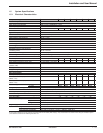
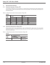
Table 1-2: Electrical Parameters for Bypass AC Source.
Electrical parameters for bypass AC source (480 V)
rated UPS current bypass AC source (1)
output rated current In for unit: for 25% for 50%
in kVA overload overload (3)
100 120 150 180
130 156 205 234
150 180 236 270
180 217 283 325
200 241 316 362
225 271 320 407
(1) The bypass AC source currents have been determined for a rated phase-to-phase voltage of 480 V, a load
power factor of 0.9 and for full rated load as well as overloads of 25% or 50%. When choosing the circuit breaker
rating, use the "rated current" column and check that the circuit breaker tripping curves are compatible with the
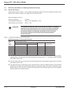
data in the overload columns. See table and chart below.
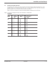
Table 1-2A:
UPS output maximum permissible current
in kVA
100 50 In for 20 ms
130 38 In for 20 ms
150 33 In for 20 ms
180 27 In for 20 ms
200 25 In for 20 ms
225 22 In for 20 ms
Figure 1-3: Fuse Curve Chart.
10
4
t(s)
I(A)
10
3
10
2
10
1
1
10-
1
10-
4
10-
3
10-
2
10
2
10
3
10
4
Introduction 1 — 786-133060-00 A00