


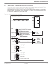

3.3 Power-Circuit Wiring Diagrams
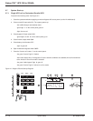
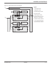
The single UPS wire diagram is for typical UPS installations shown in Figure 3-1. The heavy lines represent the
cables that must be connected (F), refer to section 3.5 ‘Connections Between Cabinets’ for more detail on cables.
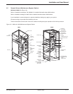
Figure 3-1: Galaxy PW™ Single UPS Unit Wire Diagram.
Legend:
1: Normal AC source,
2: Bypass AC source,
A: Rectifier/charger module,
B: Inverter module,
C: Static-bypass module,
D: Battery cabinet next to the
Galaxy PW™ UPS cabinet,
E: Additional battery cabinets,
F: The equipotential-bonding
connection between cabinets.
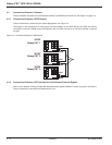
3.4 Hot Swap Options
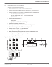
The external bypass may be used to construct a bypass outside the UPS, thus making it possible to shutdown the
UPS for maintenance purposes.
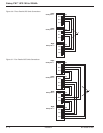
The option may be used for single UPS units and redundant parallel UPS. For the power-circuit connections of a
single UPS unit see Figure 3-2, for the power-circuit connections of parallel UPS see Figure 3-3.
Power cables for UPS-to-bypass connections are not supplied.
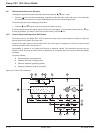
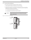
Figure 3-2: Single UPS Unit Power Circuit Connections.
Legend:
1: Normal AC source.
2: Bypass AC source.
A: Rectifier/charger module.
B: Inverter module.
C: Static-bypass module.
D: Battery cabinet next to the
Galaxy PW™ UPS cabinet.
E: Additional battery cabinets.
F: The equipotential-bonding
connection between cabinets.
Galaxy PW™ UPS 100 to 225kVA
Installation3 — 2 86-133060-00 A00
C
B
A
Q4S
Q1 Q5N
Galaxy PW
Q3BP
2
1
D
+
–
+
–
E
F
QF1
F
Q4S
2
Q3BP
Q5N
( )
( )
( )
( )
2
1
C
B
A
Q4S
D
+
–
+
–
E
F
QF1
Q1 Q5N
Galaxy PW
F
Q3BP
( )
( )