


Installation and User Manual
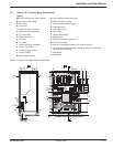
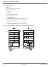
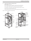
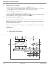
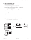
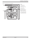
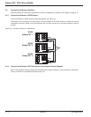
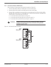
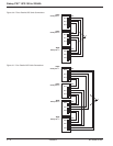
2.8 Parallel UPS Unit for Increased Output
Proceed in the following order: See Figure 2-8.
1. Check that all load devices are off or that the load is disconnected.
2. Close the upstream switch supplying normal AC source power (on the LV switchboard).
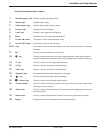
3. Close the normal AC input circuit breakers Q1 on the UPS units. The system powers up:
- the rectifier/chargers automatically start,
- the green "rectifier/charger" lights 1 in the control panels go on,
- lights 2 turn red.
4. Close the battery circuit breakers QF1.
- lights 2 go off.
- green lights 3 and 5 on the control panels go on.
5. Close Main 2 input switch Q4S for the units.
6. Close output switches Q5N for the inverters and in the external bypass unit.
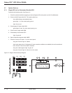
7. Open maintenance bypass switch Q3BP in the external bypass unit.
8. Press the "inverter on" button 7 on each control panel:
- the green "inverter" lights 4 flash.
9. When a sufficient number of inverters are ready, the inverter-output contactors close:
- the green "inverter" lights 4 shine permanently green.
- the "static-bypass" lights 3 go off.
Figure 2-8: Parallel UPS Unit for Increased Output.
3
1
2
1
0
1
0
7
Q5N
1
0
Q4S
Q1
Q5N
1
0
Q4S
Q1
QF1
0
I
1
0
1
0
Q1
1
0
1
0
1
0
7
8
1
2
8
7
643 521
22
5 6 7
4
Q5N
Q3BP
external bypass
1
0
1
0
1
0
1
0
System Setup 2 — 1186-133060-00 A00