


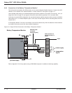
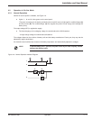
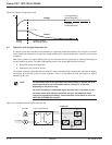
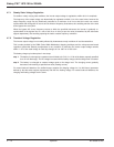

Figure 4-8: Battery Charge Cycle Chart.
4.4 Operation with Engine Generator Set
If a stand-by generator is included in the installation, it is generally started automatically in the event of a normal AC
source failure and connected to the main low voltage switchboard. It is disconnected when normal AC source power
is restored.
With such a system, the required battery time may be reduced to the time necessary for starting and bringing on
line the stand-by generator. The battery (D) supplies power to the inverter (B) during the transfers:
◗ Normal AC source to the generator.
◗ Generator to the normal AC source.
The transfer sequences described above (normal AC source ➜ battery, battery ➜ generator, generator ➜ battery,
and battery ➜ normal AC source) are fully automatic. They in no way affect the load and require no manual
operation by the user.
NOTE To avoid load surges on the generator, the rectifier/charger is started with a 10
second maximum current consumption walk-in (lasting 3 to 10 seconds,
depending on the percent load).
To avoid overloading an undersized engine generator set, it is possible to set a
maximum power level drawn by the normal AC input. Any additional power
required is supplied by the battery. This modification can be made on site by an
MGE UPS SYSTEMS field engineer
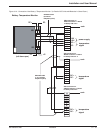
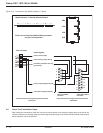
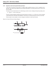
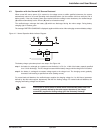
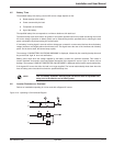
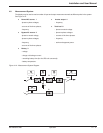
Figure 4-9: Installation with an Engine Generator Set.
HV system
Mains 2
Mains 1
Galaxy PW
G
A
B
D
C
generator
main LV switchboard
U/I
current
limiting
0,1 C10
constant voltage
decreasing current
voltage
current
t
U charge/floating
(sealed batteries)
U "floating"
(vented batteries)
Galaxy PW™ UPS 100 to 225kVA
Operation4 — 6 86-133060-00 A00