


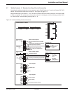
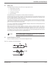

4.1.3 Single UPS Unit
The inverter starts, then, if the bypass AC source transfer conditions are satisfied, the load is transferred to the
inverter, if the on-line mode is selected.
For on-line mode:
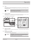
◗ The green "inverter" light 4 remains on.
◗ The "static-bypass" light 3 goes off.
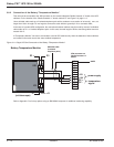
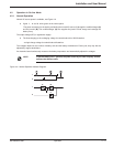
Figure 4-2: Single UPS Diagram .
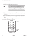
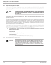
4.1.4 Parallel UPS Unit
The inverter starts and awaits the start of the other inverters. When they are all on or enough have been started to
supply the rated load power, the output switch for each running inverter closes and the load is supplied with power:
◗ The green "static-bypass" light 3 goes off.
◗ The green "inverter" light 4 on the control panels of the running inverters goes on.
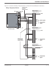
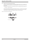
Figure 4-3: Two Parallel Connected UPS Units.
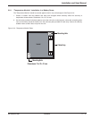
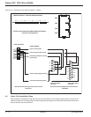
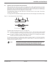
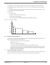
Figure 4-4: Four Parallel Connected UPS Units.
2
1
Q3BP
Galaxy 1
Galaxy 2
2
1
Galaxy 3
2
1
Galaxy 4
2
2
Q5N
1
2
1
Q3BP
S
Galaxy 1
Galaxy 2
2
2
Q5N
1
1
2
AB
C
D
Galaxy PW™ UPS 100 to 225kVA
Operation4 — 2 86-133060-00 A00