


CAUTION Work should be carried out in accordance with applicable safety regulations. to
avoid interrupting the load, the various switching operations must be carried out
in the correct order. Operations are explained in diagrams placed next to the
switches. the system cabinet is only partially powered down.The load is still
supplied via the bypass AC source and switch Q3BP.
5.3 Steps for Parallel UPS Redundancy to Increase Output
CAUTION
PARALLEL UPS WITH EXTERNAL MAINTENANCE BYPASS During mainte-
nance operation, when CB1 (MBP) is closed and CB2 (UPS ISOLATION) is
open, each UPS control panel display will show a message “LOAD
PROTECTED” when the UPS is placed in ON-LINE MODE. In this mode the
critical load is not protected because it is supplied by the maintenance
bypass power.
First Isolate all UPSs: (Refer to section 5.2, page 5—2)
See Figure 5-6.
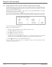
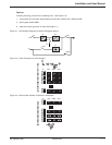
Proceed in the following order: (See Figure 5-4)
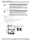
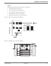
1. Shut down the inverters (press the "inverter OFF" buttons 8 for three seconds).
2. Close switch Q3BP and open switch Q5N in the external bypass unit.
3. Open switches Q1, QF1, and Q5N on the UPS units.
Figure 5-4: Isolate All UPS’s Procedures Diagram.
2 3 4
1
0
1
0
1
0
1
0
Q5N
Q3BP
Q5NQ1 Q4S
QF1
0
I
external bypass
4
5
1
Galaxy PW
1
0
1
0
1
0
1
0
1
0
6
1
0
1
0
7
8
Galaxy PW™ UPS 100 to 225kVA
Maintenance5 — 4 86-133060-00 A00