


1.4 Different Types of Galaxy PW™ Systems
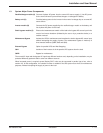
1.4.1 Single UPS System
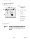
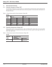
Figure 1-2: Galaxy PW™ Single UPS System.
Note: *The Fuse is to protect against catastrophic rectifier/inverter semiconductor failure.
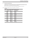
1.4.2 Parallel UPS System
Parallel UPSs can be utilized when increased power is required (two to four parallel units), or an external bypass
must be added.
CAUTION PARALLEL UPS WITH EXTERNAL MAINTENANCE BYPASS During mainte-
nance operation, when CB1 (MBP) is closed and CB2 (UPS ISOLATION) is
open, each UPS control panel display will show a message “LOAD
PROTECTED” when the UPS is placed in ON-LINE MODE. In this mode the
critical load is not protected because it is supplied by the maintenance
bypass power.
Legend:
Q1 (Molded CB NA): Isolation of
the rectifier/charger (A) from
the normal AC source (1);
rectifier/charger (A) start-up.
QF1 (circuit breaker): Battery (D)
protection and isolation.
Q5N (switch): Isolation of the UPS
(B) from the load.
Q4S (switch): Isolation of the static
bypass (C) from the bypass
AC source (2).
Q3BP (switch): Bypass switch for
maintenance.
FUE (fuses): Protection of the
rectifier/charger (A) from the
normal AC source.
FUS (fuses): Protection of the
inverter (B) from the load.
Switch Q3BP is lock on open
position on parallel UPS
systems constituted to
increase available power.
maintenance bypass:
Q3BP
inverter (B):
DC to AC
power
isolation:
Q4S
isolation and
protection:
Q5N
rectifier/
charger (A):
AC to DC
power
QF1: isolation
and protection
normal
AC input
load
battery (D):
backup power
static bypass (C):
bypass
AC input
Q1
isolation
and
protection
(1)
(2)
harmonic
fliter
*FUSE
*FUSE
Galaxy PW™ UPS 100 to 225kVA
Introduction1 — 4 86-133060-00 A00