


Installation and User Manual
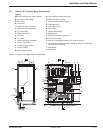
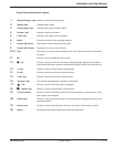
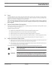
Control Panel Alphanumeric Legend:
1 "Rectifier/charger" light Indicates on/off and charging activity.
2 "Battery light" Indicates battery status.
3 "Static-bypass" light Indicates static bypass tolerance status.
4 "Inverter" light Indicates inverter on/off status.
5 "Load" light Indicates Load supplied and not supplied.
6 Buzzer The buzzer sounds in load operating situations.
7 "Inverter ON" button This button is used to start the inverter locally.
8 "Inverter OFF" button This button turns the inverter off locally.
9 -10 Keys These keys are used to select commands in the main menu and access the secondary
messages.
11 Key This key is used to validate the user’s choice.
12
øø
Key This key is used to access the main menu: display language, display-contrast setting,
sound level of the buzzer, lamp test, date and time settings, inverse-video and event log.
13 "V" Key This key is used to access voltage measurements.
14 "A" Key This key is used to access current measurements.
15 "W.Hz" Key This key is used to access other measurements:
16 "Anomaly" light This indicator light indicates the presence of anomalies.
17
⁄⁄
Key This key is used to access the primary messages.
18
ıı
"Battery" Key This key is used to access battery measurements:
19 "Forced-transfer" This key is used to voluntarily transfer the load to the inverter or from the inverter to the
static bypass (return transfer).
20 "Alarm reset" This key is used to reset stored alarms. The system accepts resetting only when alarms
have been cleared.
21 "Buzzer reset" This key is used to stop the buzzer. However, new alarms set the buzzer off again.
22 Display The display continuously indicates the system operating status.
System Setup 2 — 986-133060-00 A00