


ACCULINK 316x DSU/CSU
E-12 December 1996 3160-A2-GB22-10
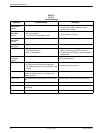
Asynchronous Port Table,
“rs232AsyncPortStopBits”
(rs232AsyncPortEntry 3)
This
object specifies the number of stop bits supported.
Only the following values are supported by the
DSU/CSU.
• one(1) – One stop bit.
• two(2) – T
wo stop bits.
• one-and-half(3) – One and a half stop bits.
Asynchronous Port Table,
“rs232AsyncPortParity”
(rs232AsyncPortEntry 4)
This object specifies the parity used by the port. Only
the following values are supported by the DSU/CSU.
• none(1) – No parity bit.
• odd(2) – Odd parity.
• even(3) – Even parity.
Asynchronous Port Table,
“rs232AsyncPortAutoBaud”
(rs232AsyncPortEntry 5)
This
object specifies the ability to automatically sense
the input speed of the port. Only the following value is
supported by the DSU/CSU.
• disabled(2) – Autobaud is not supported.
Synchronous Port Table, RS-232-like MIB
The synchronous port table contains an entry for each
of the synchronous DCE data ports and the MODEM or
COM port when the port is configured for synchronous
operation. For the T1 DSU/CSU, the entries in the table
that are counters (rs232SyncPortEntry 3–7) are used to
collect statistics and are not supported.
Synchronous Port Table –
“rs232SyncPortClockSource”
(rs232SyncPortEntry 2)
This object specifies the clock source for the port. Only
the following values are supported by the DSU/CSU.
• internal(1) – The port uses an internal clock.
• external(2) – The port uses an external clock.
Input Signal Table, RS-232-like MIB
This
table contains entries for the input signals that can
be detected by the unit for each of the synchronous DCE
data ports.
Input Signal Table – “rs232InSigName”
(rs232InSigEntry 2)
This object contains the identification of a hardware
input signal. Only the following values are supported by
the DSU/CSU.
• rts(1) – Request-To-Send
• dtr(4) – Data T
erminal Ready
Input Signal Table – “rs232InSigState”
(rs232InSigEntry 3)
This
object contains the current signal state. Only the
following values are supported by the DSU/CSU.
•
on(2) – The signal is asserted.
• off(3) – The signal is not asserted.
Input Signal Table – “rs232InSigChanges”
(rs232InSigEntry 4)
This object is not supported by the T1 DSU/CSU.
Output Signal Table, RS-232-like MIB
This
object contains entries for the output signals that
can be asserted by the unit for each of the synchronous
DCE data ports.