


Operation
3-413160-A2-GB22-10 December 1996
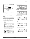
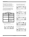
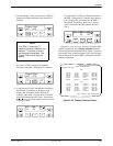
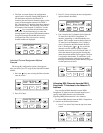
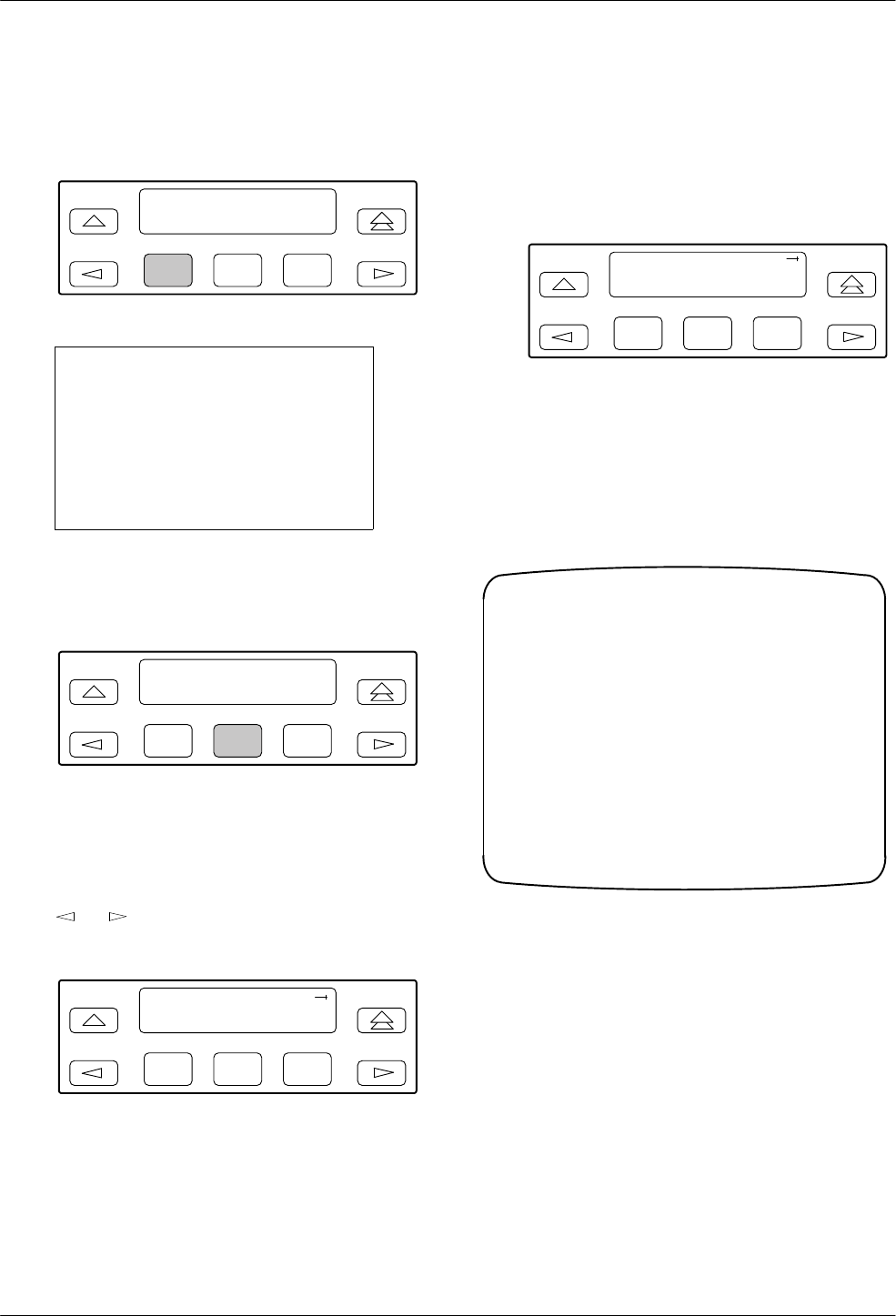
7. From the Display Chan screen, press F1 (NET) to
display the channels allocated to the Network T1
interface.
F1
Display Chan:
NET DTE
F2
F3
NOTE
If the DSX-1 Drop/Insert T1
Network interface is disabled, the
Network T1 interface channels
are displayed immediately. The
Display Chan screen does not
appear.
Or, press F2 (DTE) to display the channels
allocated to the DSX-1 Drop/Insert T1 interface.
F1
Display Chan:
NET DTE
F2
F3
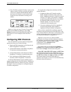
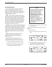
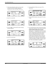
8. If you pressed F1 (NET) the channels allocated to
the Network T1 interface are displayed. Line 1
displays the 24 channels for the Network T1
interface, while Line 2 displays what is allocated
to the DS0 channel shown in Line 1. Pressing the
or
key scrolls the channels onto the screen
in groups of three.
F1
N1 N2 N3
D2 D3 Prt1
F2
F3
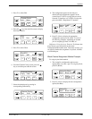
If you pressed F2 (DTE), the channels allocated to
the DSX-1 Drop/Insert T1 interface are displayed.
Line 1 displays the 24 channels for the DSX-1
Drop/Insert T1 interface, while Line 2 displays
what is allocated to the DS0 channel shown in
Line 1.
F1
D1 D2 D3
–N1N2
F2
F3
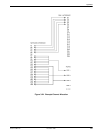
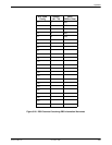
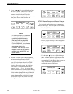
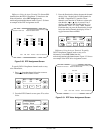
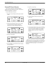
Differ
ences Using the Async T
erminal: T
o display DS0
channel assignments, select
Display Channels
from the
main/configuration/edit/channel menu. Figure 3-29 shows
an example of the screen that appears. The screen displays
both the Network T1 and the DSX-1 Drop/Insert interface
channel assignments.
Customer ID: New Cust
main/configuration/edit/channel/display
Model: ACCULINK XXXX
Main Previous Cntrl–x to Disconnect
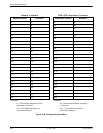
NET
N1: Prt1
N2: Prt1
N3: Prt1
N4: D4
N5: D5
N6: D6
N7: D7
N8: D8
N9: D9
N10: D10
N11: D11
N12: D12
N13: D13
N14: D14
N15: D15
N16: D16
N17: –
N18: D18
N19: D19
N20: D20
N21: D21
N22: Prt3
N23: Prt3
N24: Prt3
DTE
D1: N17
D2: Prt2
D3: Prt2
D4: N4
D5: N5
D6: N6
D7: N7
D8: N8
D9: N9
D10: N10
D11: N11
D12: N12
D13: N13
D14: N14
D15: N15
D16: N16
D17: –
D18: N18
D19: N19
D20: N20
D21: N21
D22: Prt4
D23: Prt4
D24: Prt4
Figure 3-29. Display Channels Screen