


Introduction 144
Access Server Administrators’ Reference Guide 11 • Digital Signal Processing (DSP)
Introduction
The access server uses between 12 and 60 digital signal processors (DSPs) to pass digital information. Each
DSP can accept two incoming calls, one on each “instance.” The DSPs are located on chips that contain eight
DSPs each. The access server can access these DSPs in several ways:
• On a per-instance basis—When a DSP is set to AvailableSecondOnly, the access server can disable the sec-
ond instance of a DSP.
• On a per-DSP basis—Each DSP can be set to available, unavailable, or RebootNow in order to enable, dis-
able, disabling or reboot both instances simultaneously
Note
On boards manufactured before October 31, 2001 (printed circuit board
revisions 1 or less), DSPs are rebooted on a per-chip basis. (For information
on displaying the PCB revision number, refer to
“PCB Revision (boxManu-
facturePcbRevision)” on page 233.) When a DSP is selected to be rebooted,
not only will that DSP be rebooted, but so will the other seven DSPs that are
located on the same chip. For example, if DSP1 is set to reboot, DSPs 2–8
will also reboot.
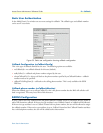
Click on
DSP
under the
Configuration Menu
to display the
DSP Settings
main window.
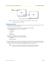
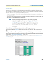
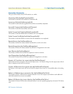
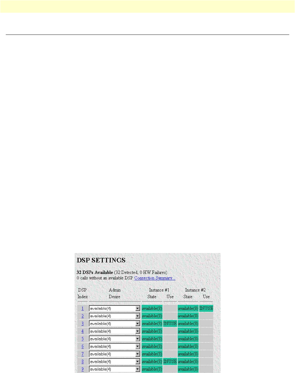
The DSP main window (see figure 59) displays the current state of the DSPs (see “DSP Settings main win-
dow”).
Clicking on the
Connection Summary…
link takes you to a page that displaying summarized statistics for the
DSPs as a group, and individual statistics for each DSP. For more information about the Connection Summary
window, refer to
“DSP Connection Performance” on page 147).
Clicking on the
DSP Index
link displays detailed information about the DSP (see section “DSP information
window” on page 151.
Figure 59. DSP main window