Alarms Present 254
Access Server Administrators’ Reference Guide 22 • T1/E1 Link
Circuit ID (dsx1CircuitIdentifier)
This is the transmission vendor’s circuit identifier. Knowing the circuit ID can be helpful during
troubleshooting.
Alarms Present
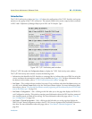
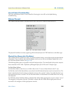
This window indicates alarms on the physical line and in the case of a PRI the status of Layer 2.
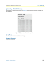
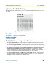
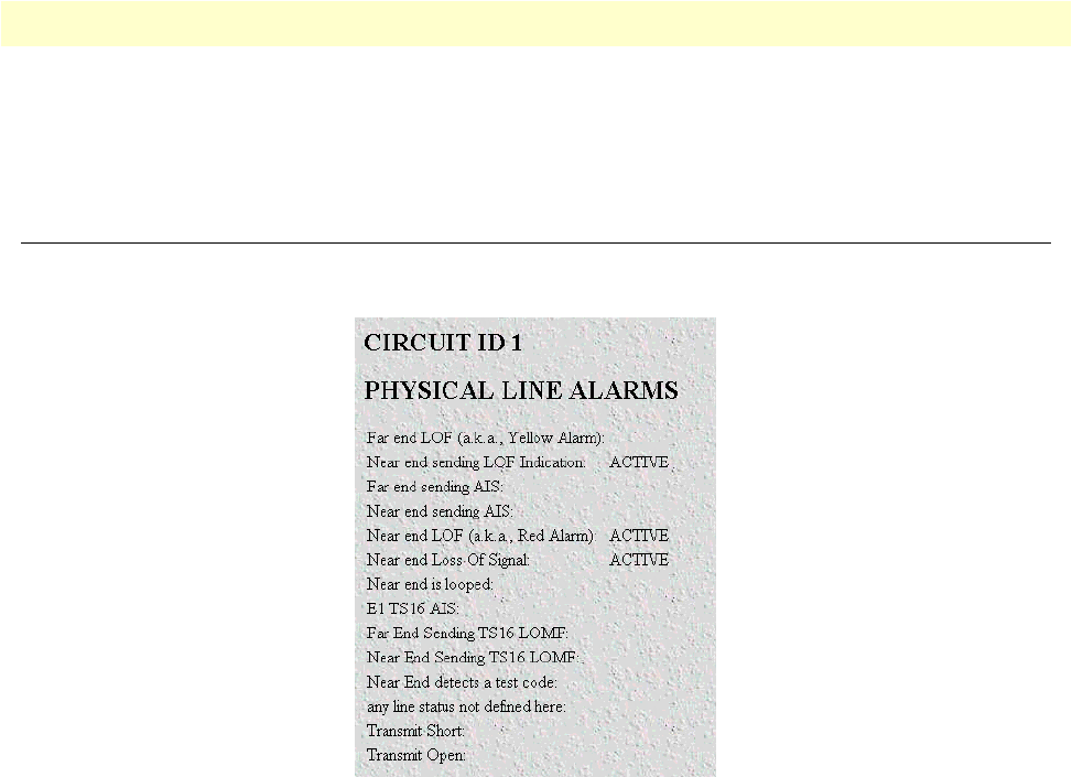
Figure 103. Line Status Alarms window
The physical line failures currently registering will be indicated by the ACTIVE label next to the failure type.
Physical Line Alarms (dsx1LineStatus)
This variable indicates interface line status. It contains loopback, failure, received alarm and transmitted alarm
information. If any condition other than
No Alarms
exists, you can click on the
Alarms Present
link to view
the Line Status Alarms window (see
figure 103).
The following failure states are reported in the dsx1LineStatus object. The items listed in this section comprise
those contained in RFC 1406—Definitions of Managed Objects for the DS1 and E1 Interface Types.
Far End Alarm Failure
Far End Alarm failure is also known as a Yellow Alarm in the T1 case or Distant Alarm in the E1 case.
For D4 links, the Far End Alarm failure occurs when bit 6 of all channels has been zero for at least 335 ms. The
alarm is cleared when bit 6 of at least one channel is non-zero for a period T, where T is usually less than 1 sec
-
ond and always less than 5 seconds. The Far End Alarm failure is not declared for D4 links when a Loss of Sig-
nal is detected.
For ESF links, the Far End Alarm failure is declared if the Yellow Alarm signal pattern occurs in at least 7 out of
10 contiguous 16-bit pattern intervals. The alarm is cleared when the Yellow Alarm signal pattern has not
occurred for 10 contiguous 16-bit signal pattern intervals.


