


Alarms Present 257
Access Server Administrators’ Reference Guide 22 • T1/E1 Link
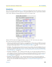
DESCRIPTION: This variable indicates the Line Status of the interface. It contains loopback, failure,
received ‘alarm’ and transmitted ‘alarm’ information.
The dsx1LineStatus is a bit map represented as a sum, therefore, it can represent multiple failures (alarms)
and a LoopbackState simultaneously
dsx1NoAlarm should be set if and only if no other flag is set.
If the dsx1LoopbackState bit is set, the loopback in effect can be determined from the dsx1LoopbackConfig
object.
The various bit positions are:
1 dsx1NoAlarm No Alarm Present
2 dsx1RcvFarEndLOF Far end LOF (a.k.a., Yellow Alarm)
4 dsx1XmtFarEndLOF Near end sending LOF Indication
8 dsx1RcvAIS Far end sending AIS
16 dsx1XmtAIS Near end sending AIS
32 dsx1LossOfFrame Near end LOF (a.k.a., Red Alarm)
64 dsx1LossOfSignal Near end Loss Of Signal
128 dsx1LoopbackState Near end is looped
256 dsx1T16AIS E1 TS16 AIS
512 dsx1RcvFarEndLOMF Far End Sending TS16 LOMF
1024 dsx1XmtFarEndLOMF Near End Sending TS16 LOMF
2048 dsx1RcvTestCode Near End detects a test code
4096 dsx1OtherFailure any line status not defined here”
::= { dsx1ConfigEntry 10 }