Configuring Non-Facility Associated Signaling (NFAS) 316
Access Server Administrators’ Reference Guide C • Technical Reference
Configuring Non-Facility Associated Signaling (NFAS)
NFAS allows PRIs to be fully utilized by increasing the number of data channels. Now PRIs can have 24 B-
channels for data rather than the traditional 23 B-channels for data and a D-channel for signaling.
The telephone company can configure a group of PRIs to share a single D-channel. In that group of PRIs, one
PRI will contain a D-channel and 23 B-channels. The other PRIs in the NFAS group will have 24 B-channels.
The request for an in-bound call now contains an interface identifier that indicates for which PRI in the NFAS
group the call is destined.
The NFAS group cannot span multiple remote access server units. Each RAS must have at least one PRI con-
figured with a D-channel.
Configuring NFAS
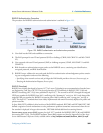
NFAS only impacts the configuration of the signaling settings. The line interface settings do not change with
an NFAS implementation.
Example 1
The RAS hosts 2 NFAS groups, each containing 2 PRIs. WAN 1 will have the PRI with the D channel. WAN
2 will have the second PRI for that group. WANs 3 and 4 will contain the second NFAS group.
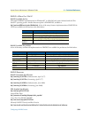
Signal setting for each WAN port
** The switch type for the primary WAN is set to the flavor of ISDN the switch is configured for. This does not
change for an NFAS implementation.
* The Interface ID must match what the central office has designated. The PRI with the D-channel must be
configure with an ID of 0. Typically, the other PRIs have interface IDs which are numbered sequentially but
the IDs can be any number up to 31.
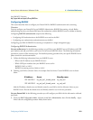
Example 2
The RAS hosts 1 NFAS group containing 3 PRIs
Signal setting for each WAN port
WAN 1 WAN 2 WAN 3 WAN 4
Switch Type
att(2)** nfsSlave(7) att(2)** nfsSlave(7)
Interface ID
0 1 0 1
Primary WAN
1 1 3 3
WAN 1 WAN 2 WAN 3 WAN 4
Switch Type
Nil (0) nfsSlave(7) nfsSlave(7) Turned off
Interface ID
0 1 2
Primary WAN
1 1 1


