


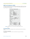

WAN Circuit Configuration—Modify 261
Access Server Administrators’ Reference Guide 22 • T1/E1 Link
Line Build Out (linkLineBuildOut)
This variable is used in T1 applications to adjust the T1 pulse shape at the cross connect point. Select the pulse
strength needed to minimize distortion at the remote T1 receiver end. The default is t1pulse0dB, which should
be adequate for most situations.
• triState(0)
• e1pulse(1)—Select for E1 configuration
• t1pulse0dB(2)—Strong pulse shape.
• t1pulse-7dB(3)—Medium pulse shape.
• t1pulse-15dB(4)—Weak pulse shape.
Yellow Alarm Format (linkYellowFormat)
This variable identifies which standard will be used to transmit and identify the Yellow Alarm.
• link YellowFormatBit2(1)—Bit-2 equal zero in every channel
• YellowFormatDL(2)—FF00 pattern in the Data Link
• YellowFormatFrame12FS(3)—FS bit of frame 12
FDL (dsx1FDL)
The framing bits used in a wide-area link that are used for control, monitoring, and testing. The following
options are available:
• other(1)—Indicates that a protocol other than one following is used.
• dsx1Ansi-T1-403(2)—Refers to the FDL exchange recommended by ANSI.
• dsx1Att-54016(3)—Refers to ESF FDL exchanges.
• dsx1Fdl-none(4)—Indicates that the device does not use the FDL.
Note
This is valid for T1 only.
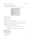
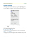
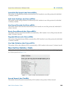
Signalling Settings
This portion of the WAN Circuit Configuration window contains information described in the following
sections.
Signal Mode (dsx1SignalMode)
• none(1)—Indicates that no bits are reserved for signaling on this channel.
• robbedBit(2)—Indicates that T1 Robbed Bit Signaling is in use.
• bitOriented(3)—Indicates that E1 Channel Associated Signaling is in use.
• messageOriented(4)—Indicates that Common Channel Signaling is in use either on channel 16 of an E1
link or channel 24 of a T1.