1 • Introduction Model 6511RC User Manual
22 Hardware overview
TDM bus architecture
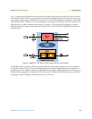
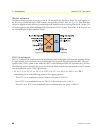
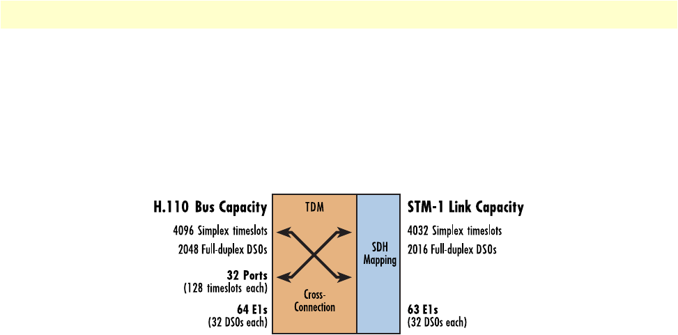
The Matrix Switch provides an interface to the H.110 bus within the ForeFront chassis.The total capacity of
the H.110 bus is 4096 half-duplex DS0 channels, the equivalent of 64 E1 lines (see figure 9). Each DS0 chan-
nel can be mapped in either direction, transmitting to the Matrix Switch or receiving from the H.110 bus. The
H.110 bus organizes the 4096 half-duplex DS0 channels into 32 H.110 ports. Each of the 32 H.110 ports car-
ries 128 half-duplex 64 kbps timeslots (DS0s).
Figure 9. H.110 bus and STM-Link capacity
STM-1 link architecture
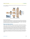
The 155.52 Mbps STM-1 uplink carries 2016 full-duplex (4032 half-duplex) DS0 channels organized into 63
E1 signal streams. Each E1 stream carries 32 full-duplex DS0 channels (64 half-duplex timeslots). The total
capacity of the STM-1 uplink on the Model 6511RC is 2016 full-duplex DS0s, the equivalent of 63 E1 lines.
The following sequence describes the process by which the Matrix Switch maps and multiplexes 63 E1 streams
into the architecture of the STM-1 signal stream:
• E1 -to- C-12 -to- VC-12 -to- TU-12 -to- TUG-2 -to- VC-3 -to- AU-3 -to- AUG-1 -to- STM-1
Multiplexing occurs at the following points in the mapping sequence:
- Three TU-12s are multiplexed into one tributary unit group-2 (TUG-2).
- Seven TUG-2s are multiplexed into one TUG-3 or administrative unit-3 (AU-3).
- Three AU-3s or TUG-3s are multiplexed into one administrative unit group-1 (AUG-1).


