


Installing the network cables 37
Model 6511RC User Manual 2 • Hardware installation
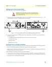
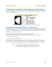
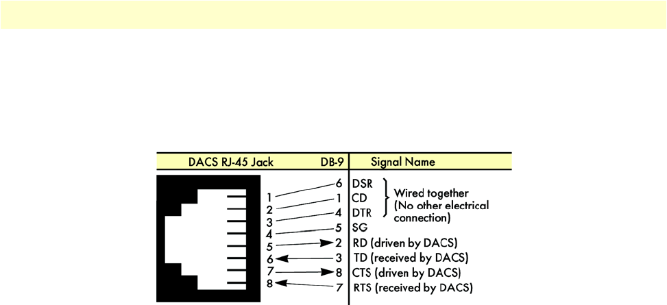
Connecting the front-panel EIA-561 RS-232 configuration port (DCE configured)
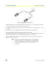
Install the supplied RJ-45-to-RJ-45 cable with the DB9-RJ45 adapter between the Matrix Switch RS-232 port
(see figure 13 on page 35) and an open serial port on your computer. If you need to assemble your own cable,
refer to the pinout diagram in figure 17.
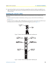
Figure 17. RJ-45 pin and signal definitions for Matrix Switch CONFIG port
Connecting the rear-panel STM-1 WAN port to an SDH network
The Matrix Switch offers two types of STM-1 interfaces—optical and electrical—presented on the rear panel of
the rear blade. Optical interfaces connect to fiber-optic network cables, while the electrical interfaces connect to
coaxial network cables. The rear-blade connectors must match the type of network cables and connectors used by
the SDH network to which you will connect.
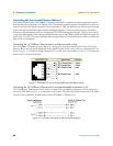
Connecting the STM-1 optical interface to fiber-optic network cables
The following versions of the Matrix Switch rear blade offer an optical interface for the STM-1 port
• Model 6511RC/M155/SC20
• Model /EBNC6511RC/M155/SC20
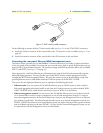
The designation SC20 in the model code denotes that an optical interface conforming to ITU specification
G.957 and G.652 is present. The Matrix Switch presents the STM-1 optical interface on a pair of SC fiber-
optic connectors, one for the transmiting (TX) and one for receiving (RX) signals (see figure 14 on page 35).
Note
The wavelength of the laser signal is 1310 nanometers. The single-
mode fiber-optic cable connecting the STM-1 WAN port to the SDH
network must extend no farther than 12.4 miles (20 kilometers).