


Hardware overview 23
Model 6511RC User Manual 1 • Introduction
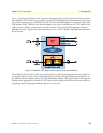
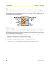
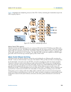
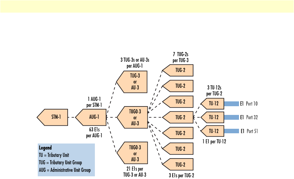
Figure 10 highlights the multiplexing structure of the STM-1 link by ommitting the intermediate steps in the
SDH mapping sequence
Figure 10. E1-to-STM-1 multiplexing structure
Matrix Switch TDM capacity
The Matrix Switch provides the means for you to map any DS0 on the H.110 TDM bus to any DS0 on the
STM-1 trunk and vice-versa. The difference in capacity between the H.110 bus and the STM-1 link is 64 half-
duplex DS0s, the equivalent of one E1 line. The STM-1 uplink provides sufficient capacity to aggregate 98%
of the traffic capacity of the H.110 TDM bus. The Model 6511RC provides the capability to map and aggre-
gate traffic on the H.110 bus up to the full capacity of the STM-1 trunk.
Matrix Switch Ethernet Switching
The Matrix Switch also delivers Ethernet connectivity and switching for any Ethernet traffic traversing the
PICMG 2.16 bus to which the blade is connected. The Model 6511RC provides the Ethernet switching fabric
for all other blades connected to the same PICMG 2.16 packet-switching bus within the chassis mid-plane.
The built-in Ethernet switch switches Ethernet traffic between the PICMG 2.16 bus, the 10/100 Ethernet
LAN port presented on the front panel of the front blade, and the two 10/100/1000 Ethernet WAN uplink
ports presented on the 6511RCrear panel of the rear blade. All three Ethernet ports provide access to the
SNMP agent and HTTP Web Management services within the 6511RC. In addition, all three Ethernet ports
provide access via the Internet Protocol to the other blades on the packet bus, including access to the Web
Management services residing within those blades. When combined with an external network management
system, the Ethernet switching feature on the 6511RC makes it possible to implement a packet-based network
management solution for all system elements connected to the same packet-switched bus in the ForeFront
chassis.