


2 • Hardware installation Model 6511RC User Manual
36 Installing the network cables
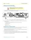
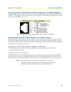
Connecting the front-panel Ethernet LAN port
The Matrix Switch includes a 10/100Base-T transceiver, accessible via a physical interface on the front panel of
the front blade for connection to an Ethernet LAN. The Ethernet interface complies with IEEE 802.3 and is pre-
sented on a 6-pin RJ-45 female receptacle. Once connected to a LAN, the Ethernet port will autosense the speed
of the LAN and automatically negotiate half or full-duplex operation. This port provides access to the Matrix
Switch’s resident management services, including the HTTP/Web Management feature. This port also connects
to the on-board Ethernet Switch, thus providing Ethernet access to other blades within the ForeFront system via
the PICMG 2.16 PSB. This section describes connecting the Matrix Switch to the Ethernet LAN via an Ethernet
hub, switch, or workstation.
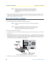
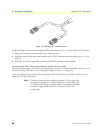
Connecting the 10/100Base-T Ethernet port to an Ethernet switch or hub
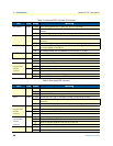
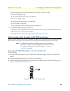
The 10/100Base-T Ethernet port (see figure 5) is designed to connect to an Ethernet switch or hub. The
Ethernet RJ-45 pin and signal definitions for the Matrix Switch or for a NIC card in a workstation/PC are
shown in figure 15. Connect a straight-through CAT-5 cable (one wired as shown in figure 15) between the
Matrix Switch and the hub/switch.
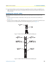
Figure 15. Ethernet RJ-45 pin and signal definitions for Matrix Switch
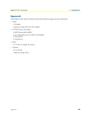
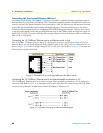
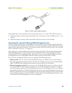
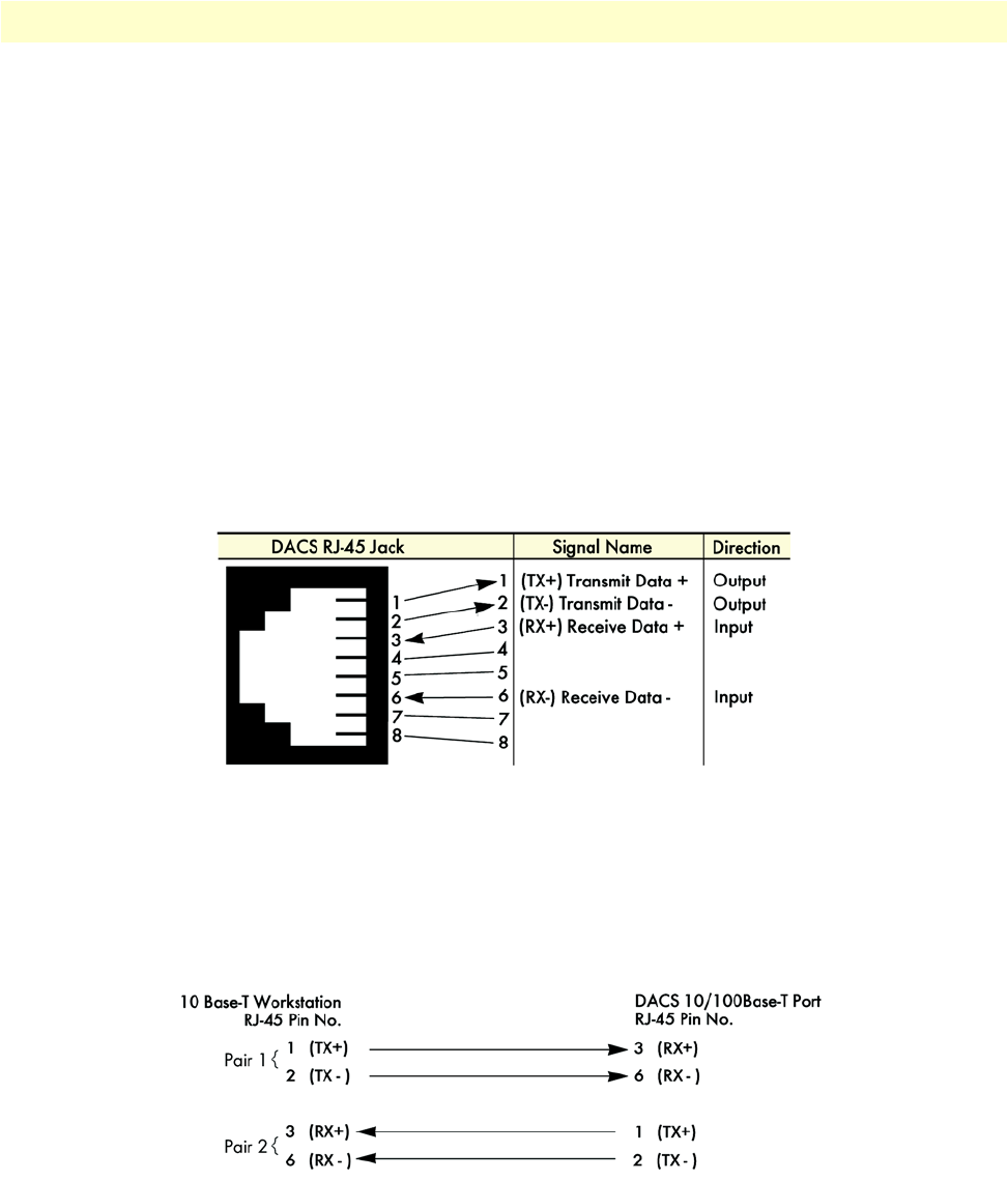
Connecting the 10/100Base-T Ethernet port to an Ethernet-capable workstation or PC
The 10/100Base-T Ethernet port can connect to a single Ethernet-capable workstation or PC by means of a
cross-over cable. Refer to figure 16 to assemble a cross-connect cable that will connect between the NIC Ether-
net port in the workstation and the Matrix Switch 10/100Base-T Ethernet port.
Figure 16. Cross-over RJ-45-to-RJ-45 Ethernet cable diagram