


Initial configuration through the RS-232 control port 43
Model 6511RC User Manual 3 • Configuring the Matrix Switch for operation
- Which E1 mapping path will be used within the STM-1 link, either AU3 or AU4.
- Section Trace Message Length
- The value of the JO byte for Section Trace Messages
- Path-1 Trace Message Length
- The value of the J1 byte for Path-1 Trace Messages
- The value of Path-1 Signal Label
- The E1 payload type, either asynchronous or byte synchronous
• To configure the DS0 mappings, you will need
- a detailed plan describing the desired source and destination for each of the 4096 simplex DS0 channels
within the H.110 bus on the chassis mid-plane
- which DS0 channels within each E1 signal stream should carry an idle code
Initial configuration through the RS-232 control port
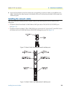
Initially you must configure the 6511RC’s IP address via the RS-232 Config port located on the Matrix Switch
front frame. In rare instances, you may also need to change the netmask from the factory default value.
Note
The Model 6511RC must be installed, powered-up, and operating
before you can perform the initial configuration. If it is not, you must
first complete the procedures described in chapter 2, “Hardware
installation” on page 31.
Connecting the DB9-RJ45 adapter with the included cable
Do the following:
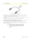
1. Find the DB9-RJ45 adapter for your PC and RJ-45-to-RJ45 cable shipped with your 6511RC Matrix
Switch.
2. Connect the DB9-RJ45 adapter to your PC’s RS-232 serial port.
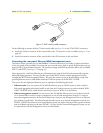
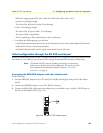
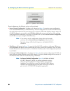
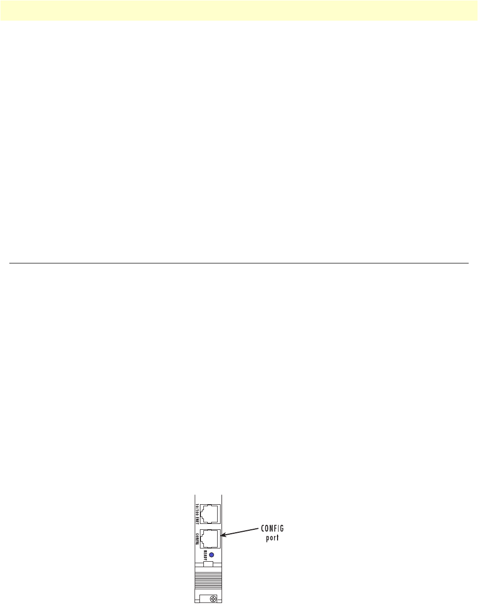
3. Connect the RJ45-RJ45 cable between the adapter that you installed in step 1 and the CONFIG port on
the front of the Model 6511RC (figure 20).
Figure 20. Model 6511RC interface ports